 My name is Wouter van Ooijen. Van Ooijen Technische Informatica (Dutch for 'technical informatics') is my one-man company. May I introduce myself? I am a software engineer, working in the technical (as opposed to administrative) side of informatics, with a strong affection for electronics. My work varies from very abstract (consultancy, architecture, design) to the lowly handwork (coding, testing, support). I have worked on industrial, space and military projects, but also on cheque processing and laboratory automation. Details of my professional career can be found in my CV. I am for hire on a per-hour or fixed-price basis. At the moment I am available for 24 hours (3 days) a week. In my webshop I sell Microchip PICmiro chips (microcontrollers) and related electronics. For the PICmiro controllers I provide some free resources, including a compiler. |
| company | Van Ooijen Technische Infomatica |
| Utrechtseweg 173, 3818 ED Amersfoort, Netherlands google earth mark | |
| telephone | (+31) 33 4621296, (+31) 6 44286985 |
| fax | (+31) 84 741 5448 |
| Chamber of Commerce | Amersfoort, 32087026 |
| bank account) | 9036008 |
| IBAN | NL57 PSTB 0009 0360 08 Van Ooijen Technische Informatica Amersfoort |
| BIC | PSTBNL21 |
| SWIFT | PSTBNL21, Postbank NV - foreign operations, Postbus 1800, 1000 BV Amsterdam 9036008, Van Ooijen Technische Informatica, Amersfoort |
| VAT nr | 1822.77.471.B01 |
| wouter@voti.nl | |
| website | http://www.voti.nl/ |
Name | Wouter Olaf van Ooijen |
Education | Technical University Delft informatics (ir) |
Born | |
Professional since | 1988 |
Functions | programmer, tester, designer, architect, consultant |
Telephone | 06-44286985 (office hours); 033-4621296 (private/evenings) |
Address | Everard Meijsterweg 36; 3817 HD Amersfoort; the |
Email | |
Website | |
Company | Van Ooijen Technische Informatica |
Updated | 27-SEP-2002 |
What is a PICmicro?
PICmicro is the brand name for a family of microcontrollers manufactured by Microchip. The PIC acronym stood for Peripheral Interface Controller, but recently Microchip has renamed their chips to PICmicro. Within this family the flash-microcontrollers (16x84, 16f62x, 16f87x) are ideal devices for hobbyists and low-volume professionals because:
| These chips are relatively cheap and easy to get. |
| These chips can be programmed and re-programmed electrically with simple circuits, and without the need for an UV-eraser (they contain EEPROM or Flash-ROM); |
| Data sheets, application notes and (assmbler) development software is freely available from Microchip; |
| There are lots of web pages devoted to these controllers, including (free) designs for simple programming hardware. |
Resources on this website
On this website you can find a number of PICmicro resources:
| Start With PICs: read this before you start using PICs |
| Tools: a compiler (Jal), programmers (Wisp, Wisp628) and an alternative for using a programmer (WLoader) |
| Projects: some designs that use a PIC |
| Miscellaneous: some other stuff, including a simple course for starting with the - now obsolete - 16x84 |
Resources on the web
 | Microchip: for PICmicro datasheet, application notes, the MPLAB assembler development environment. | |
| Ubicom: for SX datasheet, application notes etc. | ||
 | The PIClist website (follow the PIC FAQ link) contains a wealth of information and links to resources. When you can not find what you are looking for on the site you can always ask your question on the list itself. | |
 [Skip Prev] [Prev] [Next] [Skip Next] [Random] [Next 5] [List Sites] [Join Ring] | The PICmicro webring links more than 100 PIC-related websites. | |
 | The SX is a PIC clone on steriods manufactured by Ubicom. A typical PIC runs at 5 MIPS maximum, SX chips run at 50, 75 or 100 MIPS. The SXwebring links a number of SX-related websites. | |
| The Embedded webring links sites about embedded computing in general. | |
| Dontronics sells various PIC boards (simmsticks!) and other PIC-related things. |
As yet there are only a few questions, fewer answers, and no structure, And a lot of [parts in brackets] that need elaboration. But everything needs a start.
This text is copyrighted by me. Unaltered reproduction in any form is allowed, but I prefer that you don't reproduce it on your website, please use a link instead. Use it at your own risk; I do not accept responsibility for it.
You can contribute by emailing Q&A's to me. If you post them on the PICLIST I might pick them up too.
Wouter van Ooijen wouter@voti.nl
todo: crystal connections, MCLR circuit, ICSP isolation, LVP/HVP
1. What is the meaning of a PIC type number?
The main type number of a PIC consist of PIC or dsPIC followed a two-digit number, some letters, and then a two or three digit number (example: PIC16F628). The PIC/dsPIC prefix is often left out. Next there can be a letter (A, B etc) indicating a revision, an/or a letter T indicating that the chips are on a tape (SMD only). This can be followed by a dash followed by a two-digit number and/or a letter that indicates the temperature range. Finally there can be a slash followed by a packaging indication.
The first number can be 12, 16, 17, 18 or 30. 30 is for the 24-bit core dsPIC's. 18 is for PICs with a 16-bit core, 17 for PICs with different 16-bit core, 12 is for other PICs with 8 pins, and 16 is for all the rest. The 12 and 16 prefixes are used for both PICs with 12-bit and 14-bit cores.
The letter can be C or F, with some additions. C is for OTP (One Time Programmable) PICs, the F is for Flash (electrically reprogrammable) types. The 16C84 is an exception: it is EEPROM based, which is in practice the same as Flash based, yet it has a C in its typenumber.
CR (instead of just C) indicates a ROM (factory programmed) chip. CE indicates a C-type chip with a separate EEPROM chip in the same package.
An L can be added to idicate a low-voltage chip. Such chip can operate on lower voltages than their normal brothers, but often (always?) have a lower maximum clock frequency.
To summarise the letter code:
If there is any structure in the last number I have not grasped it yet.
There are some oddbal chips that do not fit the above structure, like the PIC14000 (called a mixed-signal PIC because it has some analog functions) and the PIC16HV540 (which has a build-in voltage regulator).
If you think this numbering scheme so far is totally weird I am with you. The last parts are somewhat better.
The above number is followed by a dash and a frequency and/or temperature range indication, but only when this is relevant (that is, when the PIC is available in different maximum clock frequencies or in different temperature ranges). The frequency is indicated by a two-digit number expressed in megahertz (I have only seen 04 and 20), the temperature range by the letter I (industrical) or E (Extended).
When a chip is available in [add packaging info].
2. What is a PIC?
(from http://www.voti.nl/swp)
A long, long time ago (when computer chips died when a cat came near on a dry day) General Instruments produced a chip called the PIC1650, described as a Programmable Intelligent Computer. This chip is the mother of all PIC chips, functionally close to the current 16C54. It was intended as a peripheral for their CP1600 microprocessor. Maybe that is why most people think PIC stands for Peripheral Interface Controller. As far as I know Microchip has never used PIC as an abbreviation, just as PIC. And recently Microchip has started calling its PICs microcontrollers PICmicro MCU's. Maybe they heard that PIC sounds like the Dutch word for dick and wanted to spare me the frowns from Dutch readers.
PIC is also the abbreviation of Peripheral Interrupt Controller - but that's an entirey different story.
3. What is the best PIC to start with?
That (of course) depends on your objectives.
The 16C84 was the first PIC that could be re-programmed electrically. It is no longer made, but its direct successors (16F84 and 16F84A) are. There are countless webpages and other documents about starting with the 16C84/16F84/16F84A (collectively desigated as 16x84), which can make it a good choice to start with. In that case take a 16F84A, it is the latest and cheapest version of this group.
When you are after a cheap PIC that can be used for small projects the 16F630 should be your pick. It has only 14 pins (the 16x84 has 18), but it can be used with its internal oscillator and internal reset, bringing the number of useable pins to 12 (13 on the 16x84). For a realy small project you could consider the 12F629 or one of the newer 8 or even 6 pin chips. Note that both chips have a slightly higher priced version that includes A/D.
Technically the 16F628 is the successor of the 16x84, and untill the arrival of the 16F877, the 16F630 and the smaller 18F's it was the logical choice as first PIC. It is still the first choice if you want to port a 16x84 project to a modern (cheaper) PIC.
Untill the arrival of the 18F's the 16F877 and its smaller derivates were the best choice for a PIC to do development work (lots of pins, large code space, lots of RAM). I would still recommend to start with one of these when your final aim is one of the other (smaller) 16F PICs. Note that there are now never versions of these chips with an A suffix. These are improved and cheaper, but use a different programming algorithm, so check whether your programmer and/or PC software supports them.
If you want to get into PICs with the least hassle (especially when you want to use assembler) I would recommend to start with an 18F. These chips use a newer CPU core, run faster, have more memory, peripherals, etc than the 16F's and are priced only slightly higher. The 18F4520 would be a good starting point. Like the 16F877 it has a range of smaller cousins which you could consider for your project when it is finalised.
Some say that this line of reasoning (start with a big chip so you won't be tied down by lack of CPU power, memory, pins, peripherals, etc) should be taken to the extreme, so you should start with one of the dsPIC30F chips. Personally I disagree: the dsPICs are not closely related to the other PICs (so experience with them is not much help when you wnat to use other PICs lateron), and when you need that kind of chip (in terms of CPU power, memory, etc) you should seriously consider another familiy of microcontrollers. My suggestion would be ARM, for instance one of the Philips LPC chips.
4. Is the PIC 16F628 a better choice than the 16F84?
If it is your first PIC, refer to "What is the best PIC to start with?". If not, you should by now be able to be your own judge :).
5. What's the difference between the * and *A (for *=16F84, 16F628, 16F877 etc)?
The *A is the newer version of the *. For some chips there might even be a *B version.
In most cases you will be able to use the *A chip instead of the *, but you'd better check the document that describes the differences. Go to the page on Microchips website that describes the newer chip, and get the 'migration' document.
Watch out: the 16F87*A chips use a programming algorithm that is very different from the 16F87* chips, so unless your programmer / PC software explcitly supports the 16F87*A chips you will probably not be able to program them.
6. Why do I need ICD?
ICD = In Circuit Debugger
Maybe you don't. Personally I seldom use an ICD. But I am the type that does not us a debugger for a PC program either.
But an In Circuit Debugger can be very handy when you want to run a program up to some breakpoint and then check the values of various memory locations. You can of course use a simulator (for instance the one build into MPLAB), but that has its limitations (not all peripherals are simulated, timing is different, and it is unlikely that the non-PIC part of your design is simulated).
Microchip sells the ICD and the ICD2, and there are various clones of these two on the web, both commercial and do-it-yourself. These ICDs do have some quircks, but they are supported by MPLAB, the firmware can be updated, and Microchip keeps adding support for new chips.
7. Why do I need ICSP?
ICSP = In Circuit Serial Programming (sometimes: ICP = In Circuit Programming)
The Serial part is not so important, except that it puts less constraints on your target circuit than the alternative (parallel). The important point is In-Circuit.
Because you will quickly be tired of getting your PIC out of the target circuit, into the programmer, do the programming, back into the target circuit, and resetting it. And you will probably break some pins of your precious PICs. Or do you have ZIF sockets in both your programmer *and* your target circuit?
The only reasons I found for using ex-circuit programming are series production of programmed PICs, and the devlopment of software that targets lots of different chips (like when you are developing your own programmer).
8. What's a simulator, vs. an emulator?
A simulator is a program that runs on your PC which contains a model of the PIC (or another simulated controller) in the PC's software. The behaviour of the chip is simulated from clock cycle to clock cycle according to the intended functioning of the chip.
An emulator is a small circuit board which contains one or more components which electrically mimic the chip, while built-in sensors allow you to peek into its internal workings. This circuit board is often supplied with a PIC-shaped plug on the end of a ribbon cable, which you can actually plug into the intended circuit.
The advantage of simulators is that they're cheap to produce (a copy of a program), and that you can see everything hapenning inside the logical model of the chip, as all its working features are contained in the simulator's structure. Finding out the content of a register at any cycle is not much more complicated than a printf() statement. on the downside, simulators don't tell you anything about the electrical interaction between the chip and the circuit it sits in.
Emulators are great for giving you a good idead (not perfect, mind you) of how the chip will behave inside the circuit, with all those bits of unexpected non-ideal behaviour that make electronics interesting. On the down side they're much more expensive to make, may require special interface hardware, and it's harder to get the information about what's happening inside the chip out to the PC.
9. What is the best PCB layout program?
A question that contains 'best' is suspect, especially when no constraints are given.
There are many layout programs available. From heresay it seems that *all* have a steep learning curve, so don't expect to get a good picture after a few hours of trial.
[Eagle]
10. What is the best PIC programmer?
That depends on you, especially on your time/money balance.
To start with the cheapest: check the $ic-prog and $pony-prog programs. They support many types of cheap hardware that you can build yourself. In most cases it will even work.
[Wisp628] [Warp-13] [PicAll] [PS+]
11. What is the minimum I need to get started?
Picstart Plus is good in that it will usually be the first programmer to support new devices. Not the cheapest but wil probably save you hassle in the long term.
Actually I suspect this will be overtaken by the ICD2 in being the first to support new devices. See the recent discussion on the new menu selections in MPLAB6.30 for flash updating the PS+ which you cannot yet do until a new hardware attachment is made available. Also the ICD2 allows in circuit debugging, for about the same cost as a PS+, and will run off a USB port, which may be important for folk with new machines without built in serial ports.
12. Do I need a logic analyzer?
[needs an answer...]
13. Do I need an oscilloscope?
I developed a compiler for PICs without even using a multimeter, but I am crazy. If you can afford to buy a scope do get one, even if it is only an old 1 MHz valve model. In most cases two (or more!) channels is much more important than a higher bandwidth.
14. Where are good places to get PCBs fabricated?
[Olimex]
15. How can I fabricate my own PCB? Yes (see www.electricstuff.co.uk/pcbs.html) There is no 'best' - there are many choices depending on your needs, preferences and budget. But point them at Eagle and any other easy to use low cost ones. 16. Can I do SMT without a bunch of $$? Yes. Opinions vary on what you need. My choice would be a good bright light, a magnifier and a small tipped iron, plus a pair of tweezers, preferably the "normally closed" type, and some very fine (26awg) solder. Some others prefer a broder blade-type solder to drag components to their place. If you are short-sighted you might want to take your glasses of for visual inspection :) 17. Should I use assembler, a compiler, or an interpreter? All three alternatives are in widespread use, so don't expect a simple answer. An assembler programmer can, given sufficient time, always make his program smaller, faster, etc. than a programmer that uses C or another high level language. An HLL (High Level Language) programmer can, given a fixed amount of time, realise much more functionality than an assembler programmer will be able to do. A programmer that uses an interpreter that offers intrinsic functions that match the task at hand will probably outperform a programmer that uses a compiled language. The above can be influenced a lot by existing experience or the availability of re-useable code. My personal opinion is that when you are either new to programming and want to start with embedded programming, or you want to finish a specific project in the shortest time your best choice is an interpreter or a HLL, but only when the tool provides a suitable (for your project) set of intrinsic functions or libraries. When you choose this option you are not realy programming the PIC but rather programming the abstraction presented to you by the programming envrironment When you are a more experienced in programming, want to do more than one project, and/or value the learning experience, you should use a compiler. The available libraries are now less important because you will develop your own set, and probably will enjoy doing so. Even when you don't want to learn the PIC assembly language you will still have to learn the nitty gritty details of your chip (timers, A/D, UART, I2C, PWM, etc) to make the most of it. For some time-critical things you might have to use in-line assembly. And knowing the PICs instruction set can help you even when you use a HLL, for instance to write more efficient code or to hunt a bug that turns out to be a compiler bug! When you are more familiar with assembler than with a HLL, or you want to things with a PIC that other people though realy impossible the assembler will be your tool. But if you fall into this category you are unlikely to need my advice anyway. In any case, don't let anyone frighten you away from at least trying all options. And take a look at a typical datasheet (16F877A): it is some 300 pages in all, of which the assembler instructions take only 10 pages! OK, some aspects of the CPU are described elsewhere (for instance indirection), but PIC assembler is realy quite simple. But that is not the same as simple to use. 18. Which compiler is recommended? [Jal] 19. Do I really need decoupling caps? Probably (let's say 9 out of 10 times) no. Do you need to look right and left to survive crossing a quiet street? Probably not. Is that sufficient reason not to? For those who don't get the point I also give the management summary: YES. If your chip has multiple power and/or ground pins be sure to connect them all. If the manufacturer pairs these pins it is much recommended to put a decoupling capacitor on each such pair. And a decoupling capacitor should always be as close to the pins as possible. On a solderless breadbord this might not look pretty, but if aesthetics are important to you PICs might not be an appropriate hobby anyway. The most common value for a decoupling capacitor these days is 100 nF for the capacitors close to a chip, and a 10 .. 1000 uF elco somewhere on each PCB (let's no further than 10cm from each chip). The value of this elco depends on the lower-frequency variations of the current your board draws. For most microcontroller applications 22uF will be fine. 20. Where can I get a GCC for PICs? (from http://www.voti.nl/swp) 21. Where can I get a 40 MHz crystal or resonator to run my 18F chip at full speed There are two ways to run an 18F at full speed, but neither involves a 40 MHz crystal or resonator. The first way is to use an external 40 MHz oscillator, feed the oscillator output to the OSC1 pin, and configure the chip for EC or ECIO mode. The second way is to use a 10 MHz crystal or resonator with the internal multiply-by-four PLL (HS4 mode). 22. What are the differences between the 16F628 and the 16F628A/16F648A? [Maarten Hofman on the PICLIST] The differences that I have noticed are: Note that most of these differences are either advantages or are really obscure. If your programmer can support it, using the 'A' part is the wiser choice, and the 16F648A price is about the same as the 16F628 price, which is slightly higher than the 16F628A price. I see lots of questions about this programmer and I hate to type something more than once, so I created this FAQ instead. It is a quick job, mainly to document my hack of the bootloader. Feel free to contribute requests, comments and/or additions.
There is no GCC port for PICs, and it is not likely that one will ever exist. The assumptions made by GCC about the target CPU architecture are reasonable for almost all CPU's that can be found in the world (including AVR, 8051 and 68HC microcontrollers), but definitely not for PICs. There is at least one attempt to create a free C compiler for PICs (based on SDCC), but at this moment (2002) no useable product is available.
1) there are programmers (like the El Cheapo) that can program the 16F628, but not the 16F628A/16F648A, even with modern software.
2) Some revisions of the 16F628A/16F648A suffer from a bug that requires you to basically halt your program while writing to the EEPROM memory. This is rarely an issue, as most of the time you'll be waiting for it to finish anyway.
3) The 16F628A is cheaper and can be interchanged for the 16F648A with very little effort (the 16F648A is about the same price as the 16F628, and therefore a good deal, unless your design states you don't need the additional 2KWord).
4) Some mode bits have changed (ER -> RC, BOD -> BOR, PWRT can be controlled separately, INTRC is called INTOSC, only one CP bit).
5) The Timer1 oscillator has been limited to 32.768 kHz, instead of anything up to 200 kHz.
6) The dual speed oscillator no longer works in ER mode.
7) The 16F628A/16F648A consumes a lot less power.
8) All versions of the 16F628A/16F648A can handle 20 MHz. With the 16F628 there are different versions for different frequencies. >BR>9) The 16F648A also has more data memory (256 instead of 224) and more EEPROM memory (256 bytes instead of 128 bytes). However, these are still not significant changes from the 16F628A, so my list of changes should still work fine. 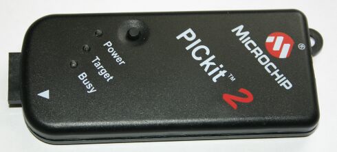
The PICkit 2 is an USB in-circuit prototype programmer manufactured (and sold) by Microchip.
The PICkit 2 contains an 18F2550 chip. This chip can update its code (write to its own FLASH memory). The PICkit 2 contains a bootloader that makes this possible. You can use this feature to update the firmware of your PICkit 2.
With the latest version of MPLAB (7.41) it should be possible to use the PICkit 2 as an ICD (in-circuit debugger, like ICD1 or ICD2), but only with the PIC16F917. So far I have not been succesfull with this.
2. What is 'in-circuit'?
The PICkit 2 is an in-circuit programmer, which means that it does not have a ZIF or similar socket to plug the target chip (the chip to be programmed) in. Instead it has a connector for a 6-pin, which you must connect to the target chip. With some care this enables you to program the target chip without removing it from its circuit. This is a big time-saver compated to ex-circuit programming (take the chip out of the target circuit, put it in the programmer, program it, take it out, put it back into the target circuit).
3. What is 'prototype'?
To be realy realy sure that a PIC is correctly and long-term reliably programmed it must be verified (by reading the code back and comparing it to the original) at the low and high extremes of the power supply voltage that it will be used with. Microchip calls a programmer that can do this a 'production' programmer. A programmer that does not have this capability is called a 'prototype' programmer, indicating that it should not be used for development only, not for production work. The PICkit2 hardware has a limited ability for varying the supply voltage for the target chip (it can only regulate down from the voltage supplied by the USB connection, and its only reference is that voltage), and the current PICkit2 software uses this ability only to reduce the supply voltage to 3.3V for chips that cannot use a higher voltage. Hence the PICkit2 is called a 'prototype' programmer.
Whether this protype/production distinction matters for programming FLASH PICs, especially when the chip is powered by a 7805 regulator (which should limit the power voltage variations to a minium) is an ongoing debate.
4. What is a 'bootloader'?
Generally speaking a bootloader is a (small) program, which sole purpose is to load another program (the application) into memory (and probably to start that application). In the context of FLASH microcontrollers a bootloader is a program that can write an application program to the FLASH memory of the microcontroller (it can of course write only to the part of the FLASH that is not occupied by the bootloader itself). The PICkit 2 contains a bootloader that will takes control when the PICkit 2 is powered. When the bootloader does not find an application program already in FLASH, or it finds the PICkit 2 button pressed, it will remain in control. Otherwise it will pass control to the application program (the PICkit 2 firmware itself).
When the bootloader is in control it will blink the Busy LED.
5. How can I download/update the PICkit2 firmware'?
The PICkit 2 XP programn supplied by Microchip has a menu entry 'Download PICkit 2 OS firmware' under 'tools'. This will instruct the PICkit 2 application to pass control to the firmware and let you pick a .hex file to be downloaded.
If your PICkit 2 contains the bootloader but no application the bootloader will remain in control (the Busy LED will blink). When you start the PICkit PC program it will take some time during which nothing seems to happen (don't panic). Then a window appears that allows you to choose the application .hex file to download. This also takes ome time. Then the normal PICkit 2 application window will appear, but it shows a nonsense message about a strange firmware version. You can ignore that message.
6. The software in my PICkit 2 seems to be corrupt, what can I do?
If an application is present in the PICkit 2 but it is corrupted (or it is not the PICkit 2 firmware) you can not use the normal software update method. Instead you must plug the PICkit 2 in (USB cable) while pressing the button. This forces the bootloader to invalidate the application and take control. Now you can proceed as stated in the previous answer.
7. What is the purpose of that button?
The PICkit2 has a small black button right above the power LED. When it is pressed while the USB connection is made the bootloader will claim control instead of activating the PICkit2 firmware. This can be used to update a damaged firmware.
The PICkit2 hardware has two 24LC512 EEPROMs. With the current firmware these EEPROM are not used. With appropriate firmware (which to my knowledge does not yet exist) the PICkit2 could be used as a stand-alone programmer: use a PC to load the software update into the EEPROMs, drive to the device you want to update, plug the PICkit2 in, press the button, and the new software is programmed into the device. The device must provide power to the PICkit2, and the target PIC must be one that can be programmed with a Vdd-before-Vpp sequence.
8. Which USB driver do I need?
You don't need a special USB driver, the PICkit 2 uses the HID (Human Interface Device) driver that is part of Windows XP and most other modern OSes (Linux, OS/2, etc). This screenshot shows the PICkit2 device as shown by the XP device manager.
9. I get 'USB device not recognised', what should I do?
This problem is often reported by PICkit 2 users. I don't have a definitive solution, but some thing seem to help:
- disconnect the PICkit 2 from the target circuit before you connect the USB cable
- plug the USB connector in slowly (this increases the time between the power contacts connecting and the data contacts connecting)
- when you get the error, disconnect, wait a few seconds, and reconnect.
- contrary to the above, some people have reported that you must wait a long time (>30 seconds?) before you attempt to reconnect. I suspect that this is a cure for a different problem.
- if the PICkit 2 is connected to a HUB, disconnect the HUB from the PC and reconnect (I still saw the 'USB device not recognised' error but the device did work!)
- (a bit experimental) during experiments with a PICkit 2 clone I am designing I noticed that the 'USB device not recognised' was produced by the PICkit 2 application, never by the bootloader, and also never immediately after the application was downloaded and started by the bootloader. The USB part of the application and bootloader work a bit different, so I reasoned that maybe the bootloader does a better job on the USB initialisation. But the original bootloader does not initialise the USB, except when no application is present, or the button is pressed. So I modified the bootloader to *always* initialise the USB, wait a second, shut down the USB, and then start the application (if present). You can hear this: when you plug it in you hear a USB attach, USB detach, and a final USB attach. So far I never got the 'USB device not recognised' with this modified bootloader. To use this bootloader you will have to re-program your PICkit 2. When you open it you will notice a strip of 6 pads at the edge of the PCB. These pads can be used to (re) program the 18F2550 in the PICkit 2 with .... a PICkit 2. Here are the files: PICkit2Bootloader_Wouter.hex and boot_main.c.
Starting with PICmicro controllers
intro, first steps, tips, links, etc.
(C) 2002 .. 2004 Wouter van Ooijen (wouter@voti.nl)
Last change:21-SEP-2003. The latest version of this document can be found at http://www.voti.nl/swp.
Unaltered duplication is allowed. Translations require approval of the author, which will most likely be granted if the quality of the translation is adequate.
This is not a fool's guide: fools are much more fool than I am clever, and fools should not program PICs (nor anything else) anyway.
I don't accept any responsibility for errors in this text or the consequences thereof, but I appreciate constructive comments.
This document is still under construction: you will find some remarks in square brackets [] where I plan to write additional text.
Audience
So you think you want to start using PIC microcontrollers? Read on! This page will offer advice on how to proceed.
Writing this page I had to make some assumptions about you, otherwise the number of options would be even larger than it is now. So if you do not match the description below, some information might be irrelevant to you, and some recommendations might not be appropriate. Be your own judge.
This page is intended for someone who
| wants to start using PIC microcontrollers but has no prior experience in microcontrollers |
| has more time than money (typical situation for a hobbyist or small-scale professional) |
| is more interested in experimenting and building prototypes than in assembling large series |
| has (at least) basic knowledge of both electronics and programming |
Note that I do not assume a master's degree in electronics or programming. But on the electronics side understanding the basic working of a resistor, capacitor, diode, LED, transistor etc., and being able to apply at least Ohm's law are mandatory. On the programming site you should have some programming experience, so terms like variable, assignment, if, while, call, goto and return ring a bell.
Starting with PICs requires you to make a lot of choices. This document tries to help you doing so, sometimes by making a strong suggestion, but always - I hope - by providing you the information you need to make the right decision for your particular situation.
If all you want is a list of pre-cooked advices don't read on, just ask on comp.arch.embedded or any other forum and you will get all possible combinations of advices, just pic one ;)
What's in a name
A long, long time ago (when computer chips died when a cat came near on a dry day) General Instruments produced a chip called the PIC1650, described as a Programmable Intelligent Computer. This chip is the mother of all PIC chips, functionally close to the current 16C54. It was intended as a peripheral for their CP1600 microprocessor. Maybe that is why most people think PIC stands for Peripheral Interface Controller. As far as I know Microchip has never used PIC as an abbreviation, just as PIC. And recently Microchip has started calling its PICs microcontrollers PICmicro MCU's. Maybe they heard that PIC sounds like the Dutch word for dick and wanted to spare me the frowns from Dutch readers.
Are you sure?
But first let's take two steps back. You think you want to start using microcontrollers? I hope you realize what you are up to. It is surprisingly easy to use a microcontroller to perform some nice tricks like flashing a LED, or even controlling a simple robot. But these simple tricks will whet your appetite for more complex applications, and then the big struggle will start. On the hardware side microcontrollers are powerful and complex chips, so you are in to some serious reading, especially of the data sheet of the chip you will be using. I know the 200+ pages of a 16F877 data sheet look intimidating, but you will have to bite that bullet some time. And when you have finished that document there is still the midrange reference manual at almost 700 pages! On the software side things can get quite complex too, especially if you want to do more than one thing at the same time. Programming is difficult, and microcontroller programming (beyond the blink-a-LED level) even more.
When all you ever want to do is blink a few LEDs, switch some relays etc. you might be better off with an environment that hides the ugly hardware details (and most of the power!) from you, like a BASIC Stamp, essentially a PIC or SX chip with a BASIC interpreter. If so, get a Stamp and put this document aside until you are in for more.
Are you really sure?
When you have decided to use a microcontroller the next step is to decide which one. This page is about PICs, but you should at least be aware that other options exist, like the Motorola 68HC, Atmel AVR, and the 8051 in all its varieties from various manufacturers. There are firm proponents of each of these microcontroller families, and probably for good reasons. Asking 'what chip should I choose' on an appropriate internet newsgroup will give you an idea of how religious this issue is to some people.
Criteria that you can take into account when choosing a microcontroller (family) are:
| availability |
| price |
| ease of use (as a start consider only controllers with flash memory that can be (re)programmed in-circuit) |
| quality and price of development tools |
| support from friends, neighbors, clubs, newsgroups, mailing lists |
| availability of application notes, reference designs, hobbyist web pages |
| features of the chip (IO pins, UART, A/D, D/A, counters, speed, code size, data size, etc.) |
| ease of migrating to smaller (cheaper) or larger (more capable) chips |
Personally I started with PICs and have not looked into the other ones much. Motorola's 68HC family is often used for somewhat more complex tasks than PICs, but tends to be more difficult to buy. The smaller AVR's are much like the PICs in price and performance. (Hence PIC-or-AVR debates tend to be very hot.) There are so many 8051 clones around that it is difficult to say something in general about this family.
OK, so you have not been scared away and are firmly decided to start using PICs. May you live in interesting times, and never say I did not warn you!
Select a PIC
So which PIC should you choose to start with? A few years ago this question was easy to answer: the 16F84 (or, before that chip was available, the now discontinued 16c84). These were the only affordable flash PICs and hence THE hobbyist PICs. You will still find lots of designs in electronics magazines and on the internet using these chips.
But recently Microchip has broadened its offering of flash chips with types that are much more attractive. In my opinion three of these are prime candidates to be 'my first PIC': the 16F628, the 16F877 and the 18F452.
The 16F628 is somewhat cheaper than the old 16F84, has twice the code size, much more RAM, a UART and some more goodies. This is the chip for simple applications.
The 16F877 is around twice the price of the old 16F84, but is has eight times the code size, much more RAM, much more I/O pins, a UART, A/D converter and a lot more. Unless your budget is very tight I would recommend the 16F877 as your first buy, otherwise you should consider the 16F628. The 16F84A (the 16F84 - without A - and the 16c84 are obsolete) should be used only to build an existing design that you do not want to modify.
The 18F452 is part of the new (16-bit core) series of PICs. It offers an instruction set that is much improved over the 14-bit (16F) PICs, improved peripherals, twice the code space and twice the speed compared to the 16F877, at a price that is only marginally higher.
I recently found a reason to prefer a 16F628 over a 16F877 or 18F452 for a particular application: the 16F628 provides a clock option where one external resistor, which carries only DC, determines the clock frequency. The 16F87x PICs provide the option to determine the clock frequency with an external resistor + capacitor, but in that case both components carry AC and practical capacitor values are very small so stray capacitance can have a big influence on the frequency. With the 16F628 it is very practical to let a potentiometer determine the speed of the PIC, which is not advisable for a 16F877.
The table below compares some PICs that can be interesting.
| chip | package | I/O | code | data | EEPROM | peripherals | MIPS | US$ | remarks |
|---|---|---|---|---|---|---|---|---|---|
| 12C509 | sdip 8 | 6 | 1k | 41 | - | osc | 1 | 1.80 | OTP |
| 12F629 | sdip 8 | 6 | 1k | 64 | 128 | osc | 5 | 1.60 | cheap |
| 12F675 | sdip 8 | 6 | 1k | 64 | 128 | a/d, osc | 5 | 1.90 | |
| 16C84 | sdip 18 | 13 | 1k | 38 | 64 | - | 2.5 | - | discontinued |
| 16F84 | sdip 18 | 13 | 1k | 68 | 64 | 6.00 | 2.5 | - | obsolete |
| 16F84A | sdip 18 | 13 | 1k | 38 | 64 | - | 5 | 4.70 | obsolete |
| 16F628 | sdip 18 | 16 | 2k | 224 | 128 | d/a, uart, osc | 5 | 3.50 | 3d choice |
| 16F870 | sdip 28 | 22 | 2k | 128 | 64 | a/d, uart | 5 | 5.00 | |
| 16F871 | wdip 40 | 33 | 2k | 128 | 64 | a/d, uart | 5 | 5.90 | |
| 16F872 | sdip 28 | 22 | 2k | 128 | 64 | a/d, mssp | 5 | 4.00 | |
| 16F873 | sdip 28 | 22 | 4k | 192 | 128 | a/d, uart | 5 | 7.00 | |
| 16F874 | wdip 40 | 33 | 4k | 192 | 128 | a/d, uart | 5 | 7.50 | |
| 16F876 | sdip 28 | 22 | 8k | 368 | 256 | a/d, mssp | 5 | 8.20 | |
| 16F877 | wdip 40 | 33 | 8k | 368 | 256 | a/d, mssp | 5 | 9.50 | 2nd choice |
| 18F242 | sdip 28 | 34 | 8k | 512 | 256 | a/d, mssp | 10 | 8.30 | |
| 18F252 | sdip 28 | 34 | 16k | 1536 | 256 | a/d, mssp | 10 | 9.00 | |
| 18F442 | wdip 40 | 34 | 8k | 512 | 256 | a/d, mssp | 10 | 9.00 | |
| 18F452 | wdip 40 | 34 | 16k | 1536 | 256 | a/d, mssp | 10 | 10.00 | 1st choice |
| SX18 | sdip 20 | 12 | 2k | 136 | - | osc | 50 | 4.00 | discontinued |
| SX28 | sdip 28 | 20 | 2k | 136 | - | osc | 50/75 | 4.40 | |
| SX48 | TQFP 48 | 36 | 4k | 262 | - | osc | 50 | 7.40 | no DIP |
| SX52 | PQFP 52 | 40 | 4k | 262 | - | osc | 50 | 7.40 | no DIP |
The price is of course an indication only, but you should be able to get a single chip for the indicated price (excluding taxes and shipping). Both the absolute and relative prices will vary between sources.
The 12C509 is still popular for hacking pay-TV or game consoles, but its role as small and cheap PIC has been taken over by the 12F629. Note that a 12C509 can be programmed only once (OTP), so you must use an expensive 12C509JW (and an EPROM eraser) for development.
The 12F629 and 12F675 are very cheap 8-pin chips, suitable for projects that do not need the larger amount of code space, data space, I/O pins, peripherals, etc. which are present on the larger (and more expensive) chips. But I do not recommend these chips for a beginner because the code space and I/O pins of the larger chips make debugging much easier.
The 16C84 was the first re-programmable PIC. It was (and still is) featured in many designs on web pages and in magazines. The 16C84 has long been superseded by the 16F84 and the 16F84A. Except for existing designs or to use existing documentation these chips should be avoided: the 16F628 offers more memory for a lower price, in the same pinout.
The 16F628 can be considered the next-generation 16F84, because it is pin-compatible with those older chips. But note that it is not fully software compatible. The 16F628 also has a smaller cousin, the 16F627 (1k code instead of 2k, not shown in the table). The 16F627 does not seem to be an attractive chip as the prices I found were actually a little higher than for the 16F628.
With 8K code space and 34 I/O pins the 16F877 is the largest chip of the 16F87x family, The 16F876 comes in a smaller package with less (IO) pins. It is about the same price as a 16F877, so it is interesting only when the larger package of the 16F877 is a problem. The 16F873 and 16F874 have less resources and use a more cumbersome RAM address mapping to be compatible with older (non-flash) PICs. The 16F870 and 16F871 have even less resources but use the same RAM addressing as the 16F877. Note that the 16F877 and 16F876 both have a UART (for asynchronous serial communication) and an MSSP (for SPI and I2C), while the smaller chips have only a UART. The 16F872 is a 16F870 but with an MSSP instead of a UART.
The 18F chips are new family of PICs, with an instruction set that is much improved over the 16F chips, with more peripherals, and more code and data space. Yet the price of the 18F chips is only marginally higher than the comparable 16F87x chips. There are variations of the 18F chips (not shown in the table) that have an integrated CAN controller - nice when you want to create a network of PIC chips.
If you can't make sense of the Microchip part numbering you are not the only one. These are the only patterns that I have found:
| The prefix 12 is for chips with 8 pins. |
| The prefix 16 is for 12-bit and 14-bit core chips with more than 8 pins. |
| The prefix 18 is for 16-bit core chips. |
| Next the letter C is for EPROM (OTP or windowed) chips, except for the 16C84 that has EEPROM, which is (for a user) almost the same as flash. |
| The letter F is for flash chips. |
| Windowed EPROM chips have a JW suffix. |
For some of the chips mentioned in the table Microchip has released improved versions, identified by appending an A to the type. Such A chips are in most aspects identical to their non-A predecessors (but it does not harm to check the data sheets or the 'migration' document), except that the programming algorithm often changed. Hence you can buy and use an A chip if it is available (they are often slightly cheaper), but check that your programmer explicitly supports the A version. Note: The 16F84A uses the same programming algorithm as the 16F84, but the A chip can run at up to 20 MHz, the non-A only up to 10 MHz.
The SX PIC clones are interesting because they provide MUCH more computing power than the Microchip PICs. On the downside the SX'es do not provide much peripherals (only a comparator and a timer), so you will need those MIPS to implement what the manufacturer call virtual peripherals. This is a nice and powerful concept, but not suited to a beginner.
So what chip should you choose to start with? As said before, first check which chips you can actually buy. Then consider whether you want to use an existing design or other document. In that case the choice has been narrowed down for you. If you already have a programmer, check which chips it supports. For the choice I recommend that you take the most powerful chip that still fulfills the above constraints. The 18F452 (the largest chip of the 18F family) would be the first choice, the 16F877 (the largest chip of the 16F87x family) the next, and the 16F628 the last.
Once you have acquired some experience with your first PIC, and you have a nice project debugged and running, it might be the right time to fit it into a cheaper PIC.
Select a language
A discussion about choosing a microcontroller might create a lively discussion on the appropriate newsgroups, but the next choice is sure to raise an outright flame war: which programming language should you use? I will not attempt to answer this question for you (the answer depends on too many factors), I will just give some criteria and present some alternatives.
Criteria that can be taken into account when choosing a language:
| which languages do you know (but beware that C for a microcontroller might not exactly be the ANSI-C you are used to on a desktop system) |
| price of the tool |
| quality of the tool |
| quality of the tool documentation |
| support for the tool (vendor, mailing list, newsgroups) |
| ease of writing (a high level language is definitely easier to write in than assembler) |
| availability of useful libraries |
| effective use of the microcontrollers resources |
The last issue (effective use of resources) can start a flame war on its own: the famous C-versus-assembler war (for C you can substitute your own favorite language). As often in such a case the answer depends a lot on the application. My opinion is:
| An assembler programmer can, given sufficient time, always make his program smaller, faster, etc. than a programmer that uses C or another high level language. |
| Given insufficient time the reverse is true. (If you are a professional programmer: When was the last time you were given enough time to write an application? If so you are probably in an industry where the size of a production run is measured in the thousands, if not more.) |
My conclusion is that for a product that will be made in large numbers assembler should be used and for a a product that is produces in smaller numbers a high level language. But that leaves the question open how large or small the series must be, and it leaves a large gray area. A good middle road is often to use a high level language for most of your code and inline assembly for the parts that are very time- or timing-critical.
Microchip provides MPLAB, a free assembler programming environment. Even when you do not want to use assembler you should get MPLAB, if only for the build-in simulator.
Various companies sell C compilers for PICs. The prices range from moderate (below $100) to out-of-the-question (at least for a hobbyist: around $1000). I have not used any of these compilers extensively, so I cannot make a recommendation.
Before you start asking around: no, there is no GCC port for PICs, and it is not likely that one will ever exist. The assumptions made by GCC about the target CPU architecture are reasonable for almost all CPU's that can be found in the world (including AVR, 8051 and 68HC microcontrollers), but definitely not for PICs. There is at least one attempt to create a free C compiler for PICs (based on SDCC), but at this moment (2002) no useable product is available.
High-Tech C provides PICC-Lite, a free demo version of their compiler. PICC-Lite targets an number of 16F chips, some with limitations. Check the Hi-Tech website for the most recent information.
BKD provides a free demo version for their CC5X, which can generate up to 1K instructions for all PIC types. This might be interesting to hobbyists, but be aware that CC5X is not exactly an ANSI-C compiler.
Bytecraft provides a demo version of their C compiler. This demo produces only a listing, so you can not use it to translate an application, but it might be useful to see how C constructs are translated to PIC assembly.
I provide the Jal compiler. Jal looks more like Pascal or Ada than C. I think Jal is a very good tool to start (and continue!) using PIC microcontrollers, but you can hardly expect me to be objective about my own creation.
So, which language should you choose? Sorry, I can't decide this one for you. Like for all choices, if you have an individual or group near you that can help you, it is not a bad choice to select the same tools. Otherwise the right choice depends a lot on your programming experience. If you have experience in a single language, you might select a PIC language that resembles it. If you don't have prior programming experience: There are people who advice assembler as the best choice to start programming, but personally I would definitely suggest a High Level Language. Or even better: forget PICs for a while and start programming on a PC, using the parallel port to interface to 'the real world'.
For those of you who take it all to seriously: a question on the PICLIST from Christopher Gill and the answer from Wagner Lipnharski.
| Hi there. I have been using PICs since last June programming in assembler, I am now looking a using the C language. What are the advantages/disadvantages of C over the assembly language. Am I right in thinking that there are built in 'modules' for division, multiplication etc. Are there any good online tutorials on programming in C for complete beginers? Christopher |
For most PICLISTers Christopher's question would be an open invitation to start the Nth C-versus assembler war, but Wagner took a more original approach:
| First you know nothing; YOU ARE HAPPY You first learn about the chip: YOU LEARN AND USE ASSEMBLY You first find out there is an easier way, so you can spare some time to watch TV: YOU LEARN AND USE C You first find out there is a simpler way, so you can spare all the time in TV, cars, girls, bars, traveling, yatch, relaxing, etc: YOU HIRE SOMEBODY ELSE TO WRITE THE CODE. You first find out your money is going fast, so you decided to do some work: YOU LEARN AND USE JAL You first find out your money is going real fast, you need to do all the work and save some code space: YOU RETURN TO WRITE IN C. You first find out it is not bad to dedicate time, by the way, writing code is a kind of hobby, so stop watching TV and leave girls alone: YOU RETURN TO WRITE IN ASSEMBLY. You first find out happines is all around: YOU LEARN ABOUT AVRs You first find out you were happy and didn't know. YOU REMOVE WinXP AND REINSTALL WIN98SE. You first find out life is a misery, and you want paradise right now. YOU REMOVE Win98SE AND INSTALL DOS6. Now, what was your question up there? Wagner. |
Select a programmer
This is yet another issue that can start a flame war, partly because there are so many options:
| There are flash and EPROM PICs. |
| There are 2 different ways to program a PIC: serial (used by nearly all PICs), and parallel (used only by some older non-flash types), |
| 2 different ways to put a PIC in programming mode (HVP and LVP), |
| one alternative to an external programmer (self-programming using a bootloader), |
| at least two ways to interface to your PC: serial and parallel, and USB is emerging as a third option, |
| in-circuit and ex-circuit programmers, |
| production programmers and prototype programmers. |
| you can either build your own programmer or buy one. |
| The SX PIC clones are programmed in an entirely different way. |
When you start using PICs you should use only flash-based PICs. Flash PICs can be re-programmed quickly, if needed without taking them from the circuit. The programming time depends (among other things) on the size of the program, but even the largest chips can be programmed in about 30 seconds. EPROM-based PICs come in two versions: cheap OTPs (One Time Programmable) chips for production, and more expensive windowed (/JW) chips that can be erased using a UV EPROM eraser. Development using windowed chips is slow and tedious: erasing requires that the chip is removed from the circuit, put in the eraser, and erasing can take 20 minutes. Then you have to put the chip back in the target circuit and hope that you still know what you were trying to do. A professional can invest in a set of windowed chips and an eraser that can erase the whole set in one go, but for a hobbyist the high price of windowed chips makes this unattractive.
A PIC programmer puts the target PIC in programming mode and then uses the programming interface pins to enter the program into the target. The PICs that are most interesting to hobbyists use two pins (RB6 and RB7) to enter the program into the PIC (serial programming). Some older PICs used a lot of pins to enter the program (parallel programming). Nearly all low-cost programmer designs support serial programming only.
There are two ways to put a PIC into programming mode:
| a high voltage (around 14V) on the MCLR pin, this is called HVP (High Voltage Programming) |
| a logical one on the LVP enable pin (RB3 or RB4) during a reset (Low Voltage Programming) |
All PICs support HVP, only a few support LVP. But the newer PICs that are most interesting to hobbyist (16F62x, 16F87x, 18Fxxx) all support LVP (but note that the 12Fxxx, 16C84, 16F84 and 16F84A do not).
LVP is both a blessing and a curse. The blessing is that it can be used with very simple programmer hardware and a single 5V supply. A typical LVP programmer uses one HCT buffer IC and interfaces to the parallel port. The curse is that the LVP enable pin (RB3, RB4 or RB5, depending on the particular PIC) is dedicated to the LVP enable function and can not be used by the application. For a new design this would not be a big issue (A 16F877 or 18F452 has 33 IO pins, which is more than adequate for most applications) if the pin was not in the middle of an 8-bit port (port B), which is on some PICs the only 8-bit port available. And for existing designs LVP is not possible when the LVP pin is used in the design. LVP can be disabled by changing a particular bit in the PICs configuration word. This bit can only be changed using HVP programming. A freshly bought chip has LVP enabled. Personally I do not use LVP.
Within the HVP programming a distinction can be made between the flash PICs and the (older) EPROM PICs. The EPROM PICs use the high voltage to power the EPROM writing, so the high voltage must be able to deliver a substantial current. Flash PICs use the high voltage only to enable the writing (a high voltage source is generated internally), so the high voltage can have a high impedance (needs to supply only a very low current). Hence some HVP programmers can handle flash PICs, but not EPROM PICs.
Microchip makes a distinction between a production programmer and a prototype programmer. A production programmer must be able to verify the correct programming (by reading the code back) at the low and high extreme of the Vcc expected in the application. This is supposed to catch the occasional PIC that is not programmed (or erased) perfectly. I have heard that such imperfect programming occurs maybe one in a thousand cases. Hence the production/prototype distinction between is not very important for hobbyists and for development, but for production it is a small price to pay to avoid an occasional problem.
In a pinch you can use most prototype programmers for an occasional production programming by using a variable power supply, manually setting the power supply to the expected extremes and verifying the correct programming.
Some of the newest PICs (16F87x) can program themselves. This makes it possible to eliminate the need for a programmer: the PC communicates with a small program in the target chip, this so-called bootloader writes the application in the (remainder of) the targets memory and starts the application. No high voltage required, no dedicated LVP pin. But there are - of course - some disadvantages too:
| you must program the bootloader into the chip before you can use it |
| the bootloader takes away some memory (typically 256 instructions) |
| some hardware is required to interface the chip to the PC, and this interfacing uses PIC pins |
| at reset there must be some way to choose between starting the application or starting the bootloader |
| an application can be incompatible with a bootloader (for instance because the application insists on using the same code space) |
Most bootloader communicate using the PICs UART and the serial port of the PC. These bootloaders are small (256 instructions), but use the two hardwired UART pins (RC6 and RC7) that might be needed by the application for other purposes.
My WLoader bootloader uses programmed (bit-banged) serial communication via a single pin (RE3) which is less likely to be required for other purposes (and can be changed easily). The disadvantage is that WLoader is much larger (1k instructions).
Programmers (including bootloaders) must interface to a PC. Typically a parallel or serial port is used. There is no big advantage in using either one except for the availability of a free port on your PC.
On the PC software is required to drive the programmer. Most programmer software accesses the serial or parallel port directly, which is not possible or very slow under some windows versions (NT, XP).
There are lots of so-called 'zero parts' serial port programmers that are not actually zero parts but can consist of nothing more than single resistor. These HVP flash-only programmers use the RS-232 levels on the serial port directly to program the target PIC. This can work, and when it does it is surely an easy way to program your first PIC (for instance to put a bootloader in it). These programmers use the RS-232 signals directly to put the chip into programming mode. This requires about 14V, provided by two RS-232 signals. Most serial ports provide -5 .. +12 (because those voltages are available from a standard PC power supply), but laptops for instance often provide much less. The RS-232 specification requires at least -5.. +5 Volt, which is not enough to put the PIC into programming mode.
The SX chips can not be programmed using a PIC programmer. There are very few (free) SX programmer designs on the web.
So what programmer should you build or buy? When you are not sure how serious your involvement with PICs will be I suggest that you start with a 16F877 or 18F452 and a bootloader. You can either
| find someone who can program a bootloader into the PIC for you |
| build a 'zero-parts' serial port programmer and use it to program a bootloader into a PIC |
| buy yourself a 16F877 from me with WLoader. |
If you have little money and a lot of time you could try one of the almost-no-components serial or parallel port programmers. When you are certain that you will program quite a few PICs it is time to select a real programmer.
I definitely recommend selecting one that can do HVP in-circuit programming and allows to program and run the application without touching the hardware (no switch etc.), but this still leaves a lot of choices. My favorite is of course my own Wisp628 programmer, mainly because it allows you to talk to your application over the same serial line you used for programming.
If you have more money to spend the Warp13 or even Microchip's PicStart+ might be attractive.
Buy a PIC
Now where can you buy the PIC chip of your choice? If you are a lucky guy your local electronics shop might have them in stock. For the rest of us mail order will probably be the only alternative. Most big mail-order companies carry a long list of PICs and there are lots of small-scale web shops that sell PICs (mine for instance). At the end of this document you can find some links.
There are actually a number of variations of each PIC: different temperature ranges, packages, maximum clock, low power version, etc. For hobbyists I recommend the standard (commercial) temperature range, DIP (or 28 pin skinny DIP) package, standard power (low power chips have a lower maximum clock), and the maximum clock frequency (4 MHz versions are a little bit cheaper but the difference is too small to be interesting). Hence for a 16F877 the full designation is 16F877-20/P, for an 28 pin PIC the designation is for instance 16F876-20/SP (SP = Skinny diP).
Clock options
A PIC has a number of clock options. For most PICs the options are:
| HS: high-speed crystal (4 .. 20 MHz) |
| XT: medium-speed crystal (200 kHz .. 4 MHz) |
| LP: low-power 32768 Hz .. 200 kHz watch-style crystal |
| RC: (external) capacitor + resistor |
Instead of a crystal a (cheaper) ceramic resonator can be used. The HS, XT or LP options can also be used with an externally generated clock, connected to OSC1. Note that for a 4 MHz crystal either the XT or HS setting can be used.
When a crystal or resonator is used two capacitors are required, from each of the OSC pins to GND. The value depends on the frequency. I use 20 pF for 4, 10, and 20 MHz. 3-pin resonators have build-in capacitors. It is advised to keep the leads from these capacitors to the GND pin short. (This makes me wonder why Microchip has on most PICs placed the OSC pins next to the VCC, and the GND on the other side.)
Some PICs have other clock options:
| The 16F62x, 12Fxxx 12C509 provide an INTRC mode that generates an internal clock of approximately 4 MHz. One or both of the pins that are normally used for the crystal can be configured for IO. This is especially important on the 8-pin chips which would - when an external crystal and reset were used - have only 4 IO pins left. |
| The 16F628 has an ER mode where an external resistor and an internal capacitor determine the clock. This mode has the big advantage over the RC mode that the external resistor carries only a DC current, so long leads can be used (for instance to a front-mounted potentiometer) without problems. |
| The 18Fxxx chips provide a PLL setting which generates an internal clock of four times the external (crystal controlled) clock. This can be used to get a 40 MHz internal clock, with only a 10 MHz crystal (note: A 40 MHz crystal is not supported). |
The internal and external RC clocks have an (in) accuracy of a few %. This is adequate for flash-a-LED applications, but either not or just barely for more timing-critical things like asynchronous serial communication.
When you build an existing design you have no choice but to follow its choice of clocking, but for your own first experiment you could use a 'low cost' clock: INTRC for a 16F628 (4 MHz), RC for a 16F87x (100pF, 10k => 0.877 MHz). Note that the RC characterization data (relation between RC values and frequency) for the 16F877 is not in the 16F877 data sheet but in section 31.3.3 of the midrange reference manual. But immediately after the 'first step' I recommend to use a crystal, and maybe use other clock options later when this fits the design better. Using the 8-pin 12C509 and 12Fxxx with an external crystal makes sense only when the remaining 4 IO pins are sufficient, and the increased accuracy of a crystal over the internal oscillator is required (or the full speed of 20 MHz is needed).
Your first target circuit
So now you have a PIC and a programmer, and you have selected a programming language. It is time to build a target circuit. When you are the bold type you could warm up your soldering iron, to build your first target circuit on perfboard or even on a home-made PCB. But if you are like me you will make some mistakes and you will want to be able to make quick modifications, so I suggest to use a solderless breadboard.
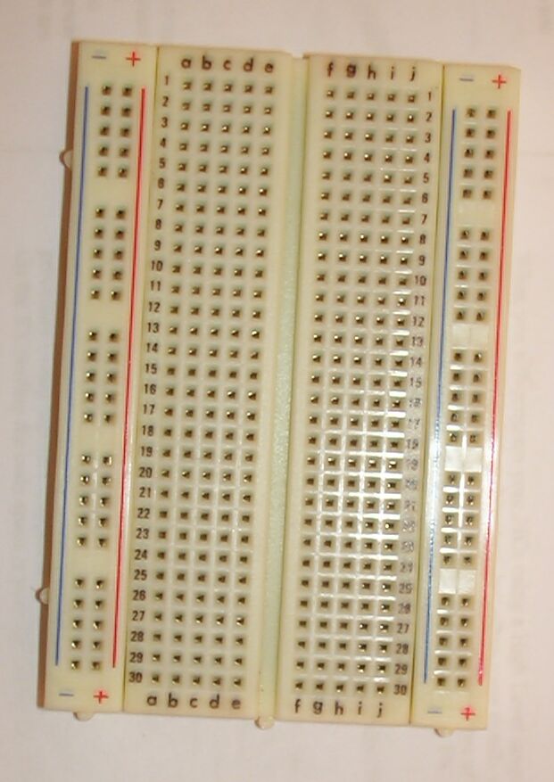 | 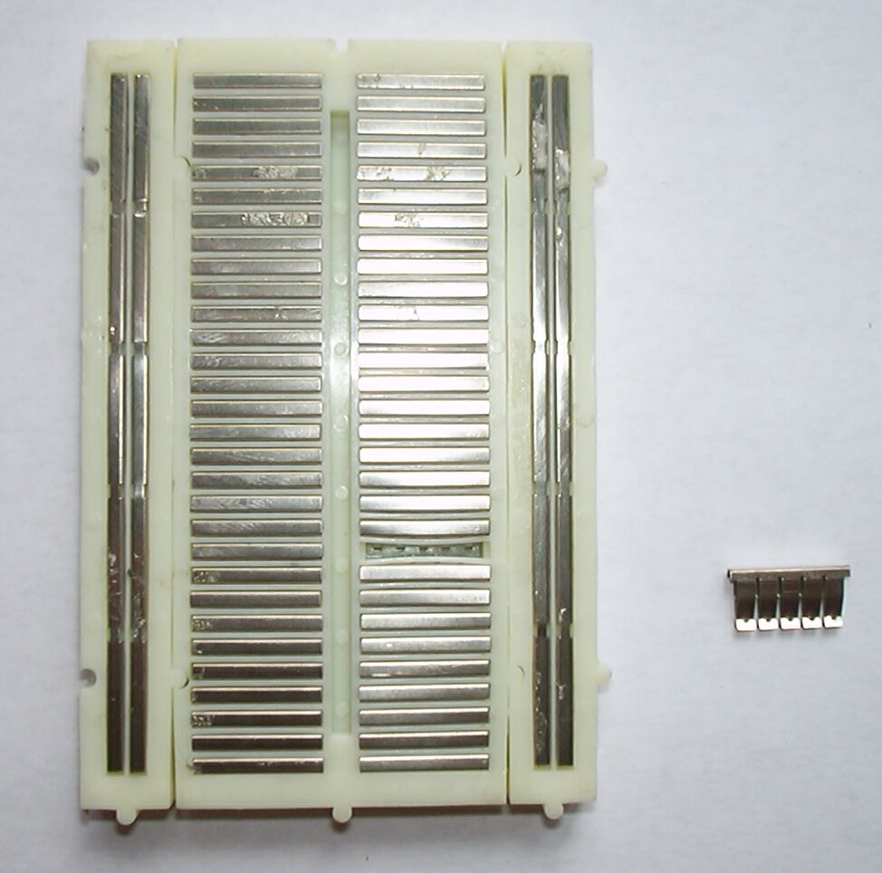 |
A solderless breadboard is a piece of plastic with a large number of holes in which you can plug your components. Beneath the holes are metal springs that secure the leads of the components and connect them together. The breadboards that I use most often consist of a mid-section where you put the components and two double power strips on both sides of the mid-section. In the mid-section the strings are connected vertically, in the power strips horizontally (see picture). Beware that the power strips often (but not always) have a break in the middle, and that the top and bottom power strips are not connected.
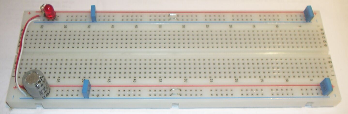
I prepare my breadboards like shown below:
| the breaks in the power strips are bridged |
| the top and bottom power strips are connected |
| a diode will short an accidentally reversed power |
| a LED shows the presence of power |
| a few capacitors (2x 100uF, 2x 0.1uF) provide power decoupling |
You will need some power for your circuit, preferably a stable +5 Volt. If you don't have a real power supply I recommend using a wall-wart (a big line plug with a transformer) plus an 7805. The circuit is dead simple (see below) and will work for all wall-warts that provide either 8 .. 24 Volt AC or 12 .. 32 Volt DC. A 7805 is both short-circuit and thermally protected, so it is difficult to damage. If you want to draw substantial current from this circuit you should use a wall wart with a lower output voltage, and put a big heat sink on the 7805.
Other options to obtain power are:
| a PC game port or USB port (your PC might be damaged when you draw too much current!) |
| a 9 Volt battery + an 7805 (be sure to disconnect the battery between experiments, otherwise the 7805 will drain the battery quickly) |
| a 4.5 Volt battery (not for the 16F84 - the one without A -, and at most at 10 MHz, preferably at 4 MHz or lower) |
The PIC architecture
When you program your PICs using a High Level language the compiler will isolate you from most details of the PIC architecture, but some details will shine through. So even when you use a compiler it is still a good idea to have some knowledge of the PIC architecture, if only to know what kind of constructs can be translated compactly to PIC instructions and which can't.
The PIC architecture is a bit peculiar, even (or especially) for people who are familiar with more mainstream architectures.
The PIC uses a Harvard architecture, which means that the code and data spaces are completely separate. Most other CPU's use the VonNeuman architecture, where code and data share a common address range. On a PIC code address 0 and data address 0 have nothing to do with each other, and can even address a different number of bits. The addressable element in the PIC data space is a byte (8 bits), the addressable element in the PIC code space is the instruction, which is 12 bits on the 12-bit cores (for instance the 12C509), 14 bit on the 14-bit cores (16x84, 16F628, 16F87x), and 16 bit on the 16-bit cores (18Fxxx).
A frequently asked question is 'how can I read (or write) the instruction at address X?'. For 12-bit and most 14-bit core PICs the answer is simple: you can't. The 16F87x and 18Fxxx PICs have a special procedure (using registers mapped in the data space) to read from and even write to the code space. On the SX reading the code space is possible with a similar mechanism, but writing is not.
On the 12-bit and 14-bit core PICs the control instructions that specify a new code location (goto and call) contain only a limited number of bits for this new location. On the PICs that have a code space that is larger than this number of bits can specify (512 instructions on the 12-bit cores, 2048 instructions on the 14-bit cores) a called code is used to get the remaining (higher) bits. The essence is that a few bits are taken from a fixed location (in the status register). Before a goto or call you must make sure that these bits are set appropriately, or your goto/call will lead your program to an unexpected location (often referred to as never-never land). The table below shows how the target address is constructed. The colons (:) mean that the various bits are concatenated. Note that there are three different cases: goto, call and modification of PCL (explained later).
| 12-bit core and SX | 14-bit core | |
| new location after a goto | [2/3 bits from status register] : [9 bits from instruction] | [3 bits from PCH] : [11 bits from instruction] |
| new location after a call | [2/3 bits from status register] : [one 0 bit] : [8 bits from instruction] | [3 bits from PCH] : [11 bits from instruction] |
| new location after modification of PCL | [3 bits from status register] : [one 0 bit] : [8 (modified) PCL bits] | [5 bits from PCH] : [8 (modified) PCL bits] |
A 12-bit core PIC has up to 2 page selection bits in STATUS, an SX up to 3 (the exact number depends on the amount of code space in the particular chip).
Note one strange detail: on the 12-bit core (and SX) one bit of the new code address after a call or modification of PCL is always 0. This means that only half the code space is accessible for these actions, and the accessible and inaccessible regions alternate. This complicates jump tables, value tables and subroutine calls.
From the table you can read that:
| As long as your program uses only the first 256 instructions you don't have to worry about code paging at all. |
| For the 14-bit cores, and when you don't touch the PCL, you don't have to worry about code paging when your program uses only the first 2k (2048) instructions. 14-bit core PICs with 2k code or less include 16x84, 16F62x, 16F870, 16F871, and 16F872. |
Turning this logic around: when you have just added a small amount of code to a perfectly working program and it suddenly starts acting weird if might be a good idea to check whether the size of your code has crossed a 'magic border' and you must start paying attention to code paging.
When the size of your code increases above the no-worries limit the simple way to keep your program working for jumps and calls is to set the page bits before each (attempted) jump or call. MPASM provides the pagesel macro to do this. The SX chips have a special page instruction that sets the page selection bits. Note that for a conditional jump or call the pagesel (or page) must be put before the skip:
   pagesel destination      ; set page bits for 'destination'
   skpnz                    ; skip if not zero
      goto destination      ; jump
The GOTO and CALL instructions on the 16-bit cores use two 16-bit 'instructions' to specify a 20 bit target address, so there is no need for code paging. There are also relative call and jump (branch) instructions that provide an 8 or 11 bit offset.
The PIC documentation calls the data space 'file registers'. You could interpret this as stating that the data RAM (file) and special purpose hardware (registers) are mapped in the same address space.
Just like the code space the PIC data space is larger than can be specified in an instruction. The same trick as for the code space is used: some bits of the effective address are taken from a fixed location, and the programmer must make sure that those bits are set appropriately, but in this case the mechanism is called register file banking. The table below shows how the effective data address is constructed.
Indirect addressing is used when an address must be calculated at run time. The calculated address is placed in dedicated special function registers, and another special function register can now be used as if it were the addressed memory location.
| 12-bit core and SX | 14-bit core | 16-bit core | |
| effective direct (instruction-specified) address | [2/3 bits from status register] : [5 bits from instruction] | [3 bits from status register] : [7 bits from instruction] | [4 bits from BSR] : [9 bits from instruction] (note below) |
| effective indirect (FSR) address | [7/8 bits from FSR] | [1 bits from STATUS] : [8 bits from FSR] | three FSRnH : FSRnL register pairs |
The SX48/52 use a somewhat different data addressing scheme. As I have no experience with these chips so I won't attempt to describe it.
The data addressing scheme shown so far has a big problem: to move data from one bank to another a LOT of bank selection instructions must be used. To reduce this problem some addresses 'map to' the corresponding address in bank 0 (or sometimes to another bank). Another way to say the same thing is that some registers appear at more than one address. The registers that map to all banks are called shared. The shared data RAM is very convenient for the assembler programmer, but there are only a very limited amount of it (typically 8 address on the 12-bit cores and 16 addresses on the 14-bit cores, and some PICs have no shared RAM at all).
The 16-bit core PICs uses the same mechanism but the data sheet describes it differently: one bit from the address provided by the instruction selects either the bank selected by the BSR, or a fixed bank that contains 256 RAM locations and 256 special function registers (on most 16-bit core PICs this includes all relevant special function registers).
When your program does not use too much data the most convenient data banking strategy is to keep the bank selection bits pointing to bank 0, only changing these bits when you must access a (probably special function) register in another bank, and then set the bank bits back immediately afterwards. Use the RAM in the higher data banks (mostly or only) using indirect addressing. MPASM provides the banksel macro to set the bank bits. The bankisel macro sets the bank bits for indirect addressing. To use this macro you must make sure that the whole data array that you are going to access is within one bank.
The PICs data memory banking with fragmented pieces of RAM makes accessing an array that is larger than the amount of contiguous RAM very tedious. For each access you will have to translate the array index to the correct bank bits and the address within the bank, and the irregular layout of the banks make it impossible to do this with just a few instructions.
The 12-bit and 14-bit core PICs have a primitive stack that is used for just one purpose: saving and storing (code) return addresses. The 12-bit cores have a 2-level stack, the 14-bit cores have an 8-level stack. The SX, which is in most aspects a clone of the 12-bit PICs, can be configured to have a 2-level stack (for maximum compatibility) or an 8-level stack (much more useful). For pushing the stack behaves like an N-entry book shelve: when you push a new address onto the stack (let's say at the left end), the oldest address (at the right end) falls off and is lost forever. For popping there appears to be a copying machine at the right end: when you take (pop) the leftmost book from the shelve the rightmost book is duplicated. Hence there are always exactly N addresses in the stack.
The 16-bit core PICs have a 32-entry stack that can be read from and written to. This means that these chips can support a real (preemptive, non-cooperative) multi tasking kernel, which is not possible on the 12-bit and 14-bit PICs.
Some stack-related FAQs:
| How can I clear the stack? There are clever methods to do so, but unless you are doing something very very clever there is no need to initialize or clear the stack. And if you are doing something that clever you will find clearing the stack a triviality. |
| Is it bad to overflow the stack? No. But it is bad to underflow the stack, because that means that you are (probably) returning to somewhere you did not intend to return to. In most cases overflowing the stack will mean that you will underflow it later, but not always. Suppose you have a main program that calls a function, and the function will never return because it loops forever. The return address of that call will never be used, so no harm is done when it is lost. In assembler you could of course have used a jump instead of a call, but in a high level language that is probably not possible. |
| Can I use the N stack levels for call/return? On the 14-bit cores the stack is used for call/return AND for interrupts, so when you use interrupts only N-1 levels are available for call/retrurn. On the 12-bit cores there is no interrupt, so the 2 stack levels are available for call/return. On the SX there is a dedicated location for storing the interrupt return address, so the 2 or 8 stack levels are available for call/return, whether interrupts are used or not. On the 16-bit cores the stack is accessible, so you could enlarge the stack by saving and restoring stack entries. |
| How can I push/pop data? You can't. Parameters must be passed to subroutines in RAM. On the 16-bit core PICs you can push and pop data, but using this mechanism to pass parameters is not effective. |
| How do I know that my program does not overflow the stack? Most high level languages will warn you. You can use the simulator build into MPLAB to run your program. Or you can just use your own intelligence: construct the call tree of your program, which is a good idea anyway. |
| My program overflows the stack. What can I do? First make a call tree of your program to find out the problem area(s). Now determine if the problem is real (see explanation about never-returning functions). If there are real problems you could - change your program structure to use less call levels - inline some subroutines - use goto/goto instead of call/return for subroutines that are called only once When this does not help there is the advanced trick of the computed return: - before the call set a variable to indicate the return point - use a goto instead of a call - instead of the return use a computed goto or one or more if's to jump to the correct return point When you don't understand this very short description you should probably not use this technique. Note that some compilers will use this technique automagically. |
Once you have mastered the paging and banking the actual PIC instruction set is very simple to understand. The processor is byte (8 bit at a time) oriented. There is one special register, called the W register.
The diadic (two-operand) arithmetic instructions have two forms. The first form operates on a memory location specified in the instruction, use the W register as second operand, and can store the result either in the memory location or in W. The second form operates on an 8-bit constant, uses the W register as second operand, and stores the result in the W register. The arithmetic operations that can be done in both forms are add, subtract, and, or and xor. Note that W is the second operand, not the first. This makes a difference for subtraction only, but has confused many people.
There is a status register that reflects the zero, carry and digit-carry status of the last calculation. Add and subtract affect all three flags. Rotate involves the carry bit. The others affect only the zero flag, except swap nibbles which affects no flag at all. For subtracting the carry flag is set when no carry occurs and cleared when a carry occurs, so it is often referred to as the carry - /borrow flag: carry refers to the carry for addition, /borrow refers to the negated (the /) borrow for subtraction.
In the tables a represents an address, [ a ] the (byte) content of that address, n a (byte) literal, b a 3-bit literal (a bit number, 0..7), and X : b represents bit b of X.
| op | mnemonic for | notes | ||
| W := [ a ] op W | [ a ] := [ a ] op W | W = n op W | ||
| add | ADDWF a, W | ADDWF a, F | ADDLW n | affects Z, C, DC |
| subtract | SUBWF a, W | SUBWF a, F | SUBLW n | affects Z, C, DC |
| and | ANDWF a, W | ANDWF a, F | ANDLW n | affects Z |
| or | IORWF a, W | IORWF a, F | IORLW n | affects Z |
| xor | XORWF a, W | XORWF a, F | XORLW n | affects Z |
Monadic (one-operand) calculations can only be done in the first form: increment, decrement, rotate left, rotate right, swap nibbles, and (!) move.
| f | mnemonic for | notes | |
| W := f( [ a ] ) | [ a ] = f( [ a ] ) | ||
| increment | INCF a, W | INCF a, F | affects Z |
| decrement | DECF a, W | DECF a, F | affects Z |
| rotate right | RRF a, W | RRF a, F | involves C |
| rotate left | RLF a, W | RLF a, F | involves C |
| swap nibbles | SWAPF a, W | SWAPF a, F | affects no flags |
| move | MOVF a, W | MOVF a, F | affects Z |
There is an instruction that loads the W register with a literal, and an instruction that saves the W register to a memory location. These instructions do not affect the flags. The instruction that loads the W register from a memory location has already been listed as an arithmetic instruction instruction: it affects the zero flag, and its destination can be either the W registers or (!) the memory location.
| operation | mnemonic | notes |
| W := n | MOVLW n | - |
| [ a ] := W | MOVWF a | - |
| W := [ a ] | MOVF a, W | affects Z |
There are instructions that clear the W register or a memory location. Both set the zero flag.
| operation | mnemonic | notes |
| W := 0 | CLRW | sets Z |
| [ a ] := 0 | CLRF a | sets Z |
There are bit set and bit clear instructions set or clear a single bit in a memory location. Note that both the memory location and the affected bit within the memory location are encoded in the instruction. For the memory location indirect addressing can be used to affect a calculated address, but there is no one-instruction way to affect a calculated bit within a byte.
| operation | mnemonic |
| [ a ] . b = 1 | BSF a, b |
| [ a ] . b = 0 | BCF a, b |
There are bit-test-and-skip instructions that skip the next instruction when a single bit in a memory location is either clear or set. A strange omission is that the W register is not memory-mapped, so testing a bit in the result that is in W is more complicated than testing a bit somewhere in memory. The status register is memory-mapped (and mapped into all banks) so the bit-test-and-skip instructions can use the status flags. As for the bit set and clear instructions both the address and the bit are constants encoded in the instruction.
| operation | mnemonic |
| skip next instruction when bit N at address A is set | BTFSS A, N |
| skip next instruction when bit N at address A is clear | BTFSC A, N |
There are special increment and decrement instructions that look a lot like the increment and decrement already described, but these forms do not affect the zero flag, but skip the next instruction when the result is zero.
| operation | mnemonic | |
| skip next instruction when bit N at address A is set | BTFSS A, N | |
| skip next instruction when bit N at address A is clear | BTFSC A, N | |
| [ A ] := [ A ] - 1 or W := [ A ] - 1 skip next instruction when result is 0 | DECFSZ a, F DECFSZ a, W | - |
| [ A ] := [ A ] + 1 or W := [ A ] + 1 skip next instruction when result is 0 | INCFSZ a, F INCFSZ a, W | - |
For control there are unconditional goto and call instructions, and a return to terminate a call. These can be combined with a bit-test-and-skip instruction to create conditional flow of control.
[ goto call return retlw sleep crlwdt retfie mpasm specials skpz skpnz ]
The PIC instruction set itself does not support indirection (the use of a calculated address). Instead two memory mapped registers are used: the FSR register acts as pointer, the INDF 'register' acts as if it were the registers who's address is currently in FSR. This is roughly equivalent to indirection as it is available on other architectures, but with only a single pointer register.
[calculated jumps]
The instruction set has some funny irregularities, that can either be seen as annoying design mistakes or as opportunities to write clever code. The add and subtract instructions do not take the carry into account, so multi-byte arithmetic is cumbersome (but there is no carry to worry about when adding or subtracting the first - or only - byte).
The 12-bit core lacks a few instructions compared to the 14-bit core:
| There is no return instruction, only a return-and-load-W. |
| There are no interrupts, so there is no return-from-interrupt. |
| There are no literal forms of add and subtract. |
The PIC instruction set can both be effective and powerful, resulting in very compact and fast code, or cumbersome and deficient, resulting in bloated and slow code. It all depends. The PIC instruction set is very good at the bit-manipulations and byte-sized arithmetic that are typical for small controller applications. The problems arrive when either multi-byte arithmetic is needed or the code and/or data is so large that the paging and banking gets in the way. This typically happens when more complex calculations or larger data sets (both comparatively speaking) are required. The use of a compiler will often shield you from the ugly details, but it can not hide the large amounts of code required to do things that can be done with much less code on more mainstream architectures. On the other hand good compilers will take advantage of the power of the PIC instruction set for simple operations.
To illustrate the weak side of the PIC architecture imagine an application that requires random access to a 120-byte array. There are PICs that have 120 and more bytes of RAM data, but this is spread over four memory banks, none of which contains 120 bytes of data. So the data access routine has to figure out, for each byte, in which bank the byte is, set the banking bits appropriately, and to the address according to the starting address of the data fragment in that bank. Store the adjusted address in FSR and the byte can be accessed in INDF. But to access the next random byte this whole procedure has to be done again. Contrast this with the very simple way in which a small array that fits in one bank can be accessed: set the bank bits, add the start address of the array within the bank and the index, move the result to FSR and use the byte in INDF. To access the next byte just change the FSR accordingly.
When you argue that you will use C and be shielded from these details you might be in for an unpleasant surprise: most compilers do not support arrays spread over multiple banks (some don't even support banking at all), and those who do will still produce the same large code that you would produce by hand, slowing down your application.
My conclusion about the PIC architecture is that for PICs the relation between 'application complexity' and 'engineering effort' is much less smooth than for more regular architectures (especially due to paging and banking). This means that PICs will often do well (read: as good as or better than other architecture) for smaller applications, but do not so well (read: worse than other architectures) for larger applications. But a lot of experience is needed to rate an application's complexity before applying this rule, it is certainly not just the amount of code, data or MIPSs.
[ FSR maps? ] [need more on 18F instruction set]
Your first program
Your first application should definitely be a blinking LED (the microcontroller equivalent of 'hello world'). When the LED blinks you have proof that your programmer and target circuit work OK. This blink-a-LED is also your fall-back when nothing seems to work and you start suspecting the PIC, the clock input, your power supply, programmer etc, your sanity, etc.
Blink-A-LED programs for the flash PICs that I have are available on my Wisp628 page.
16x84 to 16F628
In magazines and on the internet you can find lots of designs that use the now obsolete 16c84, 16F84 or 16F84a. At the moment you can still buy a 16F84a, but the fact that this chip is now more expensive than the more capable 16F628 is a clear indication that it is nearing its retirement. So you might find yourself facing the task of porting an existing 16x84 design to the 16F628. This requires some modifications and re-compilation or assembly of the program. Here we deal only with code written in assembler, which will be the most common case.
The programming model of the 16F628 is in most aspects upwards compatible to the 16x84 (more program memory, more RAM data memory, more EEPROM data memory, more clock options, more I/O options). The differences between the 16x84's and the 16F628 that must be taken into account are:
| The Vcc range for 16F628 stops at 5.5 Volt, while older PICs could handle up to 6.0 Volt. When the circuit really requires working above 5.5 Volt you will have to adapt the circuit or stick with the original PIC. My original Wisp programmer is an example of such a problematic circuit: it varies the Vcc of the PIC over a range that includes 6.0 Volt. Bad luck, moving to a 16F628 requires a redesign. |
| A topic that is a bit fuzzy in the PIC data sheets is the maximum positive voltage that RA4 (open collector) can tolerate. For old PICs this parameter is not documented, but I heard from a Microchip guy that it could handle up to around 15 Volt. The 16F628 data sheet mentions 14 Volt as absolute maximum, 8.5 Volt operational. I am not sure whether this is a difference between 16x84's and the 16F628 or just a (conservative) documentation update, but be aware that there could be a problem. |
| The configuration options (configuration fuses word) is very different for 16x84 and 16F628. In most cases the configuration word is specified as the sum of a set of pre-defined constant, so re-assembling for a 16F628 will produce a correct configuration. But when the configuration word is specified as a literal you will have to unravel it to its symbolic components. |
| The address of the special function registers on the 16x84 and the 16F628 are quite different. When the program uses the symbolic names defined in the standard include files this will be taken care off automatically, but when the SFR addresses are coded explicitly you will have to do the translation by hand (and it might be a good idea to translate to the symbolic names). Note that on a 16x84 almost all interesting SFRs are in bank 0 (so you can almost ignore banking), but on a 16F628 the EEPROM access SFRs are in bank 1. Apart from that all the SFRs on the x84 are in the same banks on the 628, but not that a 16F628 has many more SFRs and hence the GPRs (RAM) start at a different (higher) address. |
On a 16f628 the reset condition for port A is analog mode, which does not exist on a 16x84. To make port A behave as on a 16x84 insert the following code: |
Tips and pitfalls
OTP / Windowed PICs
| Some PICs (12C509, 12Fxxx) have a calibration value in the highest code location. When the internal RC oscillator is used (which will often be the case) this constant (actually a movlw instruction) is used to get the best possible accuracy of the clock. A windowed PIC has the calibration constant stored at the same location, but erasing the chip will also erase this constant. Use a programmer to read the calibration value and write it down, the bottom of the chip might be a good location. |
| The code protection of OTP PICs is controlled by an EPROM cell, just like the executable code. To prevent erasing the code protection bit before the code itself is fully erased Microchip has assured that this bit is either not erasable or very hard to erase. So when the code protection bit of a windowed PIC is set you are either one windowed PIC down, or it will have to stay in the eraser for a very long time. Advice: never enable code protection while developing! |
| Light through the window of a windowed (/JW) PIC can affect the (initial) state of the PICs RAM. This can cause differences in behavior between the windowed (development) and OTP (production) PICs. Advice: cover the window with something that is REALLY opaque, and/or make sure you initialize all variables. |
IO
| Most PIC IO pins can be used either as input or as output, and when used as output can both source and sink current. But some pins can be used only as input, for instance MCLR on a 16F628 configured for internal reset, and some pins can only sink current (open collector / open drain), this is the case with RA4 on most PICs. |
| On PICs that support LVP programming the LVP pin should be tied to Gnd during HVP programming, even when LVP is disabled. Whether HVP will fail when this is not done is unsure and seems to depend both on the PIC type and on the revision, but the safest bet is to tie LVP down. Note that a different pin is used for LVP on the 16F628 (RB4), 16F87x (RB3) and the 18fxxx (RB5). When LVP is enabled the LVP pin must of course always be tied low during normal operation of the PIC. |
| On 14-bit core chips that have analog capabilities the pins that can have an analog function default to that analog function. This is not a coincidence: when a digital IO pin is tied to a voltage somewhere between high and low this can cause the internal circuits to drawn much more current than when IO pin levels are well-defined. A digital signal on an analog pin is no problem, but the reverse is, so the pins default to analog. But this means that for digital use such pins must first be configured for digital use! This applies especially to port a on the 16F628 and 16F87x. |
| Contrary to the analog functions, which are generally enabled by default, most digital special IO functions (UART, I2C, PWM etc) must be enabled before they can be used, and often the pin must also be configured for the appropriate direction. When using a special digital function it is advised to read both the section on those functions, and the section on the IO port and pin. |
| For some purposes (I2C for instance) open-collector (or open-drain) IO pins are needed. Most PICs have one such pin (RA4), but other pins can be used in this mode by writing a 0 to the pin itself and then writing the desired IO state to the tris (direction) register. A 0 in the tris register happens to set the bit to output, so writing to the tris mimics writing to an open-collector output pin. |
| A 16F628 does not have an A/D converter, but when all you want is to control the speed of an application you can use the ER (external resistor) clock configuration and use a potentiometer. The data sheets do not specify the relationship between the resistor value and the clock frequency, but measurements indicate that 10k gives around 8 MHz, dropping roughly linearly to 80 kHz for 2M. |
| Some PIC data sheets mention a TRIS instruction and warn that this instruction 'should not be used for compatibility with future products'. Although not using the TRIS instruction might be a good idea when you want maximum portability, it is a useful instruction (it can avoid some bank switching), it is still supported on most 14-bit core flash PICs (it even works on th 16F87x which do not document it), and it will of course continue to be supported on all PIC types that currently support it. So decide for yourself whether to use or avoid it. |
| PIC IO pins have a primitive protection, consisting of diodes to Vcc and Gnd. These diodes are certainly not meant to carry significant currently, and it is a continuing debate whether they are designed to carry any current at all during normal operation of the chip. A funny consequence of these diodes is that when the power to a PIC is removed but one of its inputs is still high, it will be powered via the protection diode! This is not a guaranteed operation, but it can ruin an attempt to reset the PIC by removing the power. |
| PICs use a funny IO architecture where a reading of a pin always returns the current external level of the pin, which can be different from the last value written to a pin, even when the pin is set as output, for two reasons: - PIC instructions execute in a pipeline, and for IO pins the read part of the next instruction takes place before the writing of the previous instruction. - the load on the pin can be too high for it to reach its 'desired' level. This can easily happen (for a short time) when the load is capacitive. All PIC byte instructions that modify some bits in a byte are read-modify-write instructions, so when two consecutive BCF (bit clear) instructions on an IO port are executed the second instruction can ruin the effect of the first because of the first reason. Actually a BCF instruction (and a lot of other instructions, like INCF) on a port can ruin any previous setting of that port because of the second reason! It should be noted that the first reason occurs far more often and can be avoided by placing a NOP or another instruction between any two read-modify-write instructions on the same IO port. But to really avoid all problems it is advised to allocate a separate register, do manipulations on that register, and copy it to the port register after each change (shadow register). |
| Microchip calls the (only) IO port of the 8-pin PICs GP (General Purpose). For consistency with other PICs it might be easier to think of this port as port b. |
Assembly
| 12-bit core PICs (for instance 12C509) do not have a RET instruction. Yet the assembler accepts the RET mnemonic, and translates it as 'RETLW 0', which clears the W register. This can be an unpleasant surprise to a programmer who is used to a 14-bit core, where the W register can be used to return a calculated value. |
| Most instructions that operate on a file register can leave the result either in the same file register or in the W register. This is indicated by ',f' or ',w'. But actually f and w are just pre-defined constants, so the assembler accepts strange things like 'INCF w,w' which is interpreted as 'INCF 0,W'. When the ',f' or ',w' is omitted the assembler uses a default. I always forget what it is, so it is advised always to specify the target. |
| A radix (base) of a literal without an explicit radix specification is determined by an assembler option! Hence the only way to make sure that someone else can assemble your program (and get the same result) is to specify an explicit radix for each literal. To make sure that you have done so you could assemble with both (hex and decimal) defaults and check that the produced .hex file is the same. |
| Some things that appear to be PIC assembler instructions are actually macro's that can generate a number of instructions, not necessarily one. Funny things will happen when you try to skip such a macro-instruction: when it has generated more than one instruction you will skip only the first, when it has generated zero instructions you will skip the next instruction! [list those multi-instruction macro's] |
Documentation
The information about a particular chip is spread over a number of documents:
|
| The data sheet electrical characteristics contains a section called absolute maximum ratings. These figures indicate the circumstances which a chip will survive. Don't interpret these absolute maximum ratings as normal operating conditions. |
| The electrical characteristics document the circumstances for which the chip is guaranteed to work. This does not mean that it necessarily won't work when one or more of these characteristics are violated, just that the manufacturer does not guarantee it. For an one-off hobby project you could exceed some characteristics, test your circuit, find it working, and use it. For a very large production run you could do the same, but with much more testing. In between these extremes I would advice you to keep well within all characteristics. |
| Most PICs are sold in two speed grades: the maximum speed (currently often -20 for 20 MHz), and a 'lower grade', often -04 for 4 MHz. The 4 MHz version is often a bit cheaper. These two grades of PICs are made in the same process, using the same design, so one could reason that having two grades is just a marketing trick. All people I have heard of that have tried to run a -04 at the higher clock speed have reported success. On the other hand none of them can have applied the same tests Microchip will do on their chips (which alone might account for the price difference). So on the question 'can I use my 16F628-04 at 20 MHz': if you are a hobbyist: you are free to do so, and the chance that it will work OK (especially at 5.0 Volt Vcc and room temperature) is very high. There are reports of successful PIC over-clocking by a factor of almost 2 (a 16F84-10 at 18 MHz). But using a -04 at 20 MHz is still operating outside the guaranteed parameters, so for a professional product it should probably be avoided. |
Hardware
| Put a 0.1 uF decoupling capacitor near the power connections of each chip, and a 100 uF (or 1000 uF when larger currents are to be expected) on the breadboard. These capacitors might not always be needed, but it is a waste (even for a hobbyist) to spend days tracking down a problem caused by insufficient power decoupling. |
| I put all my chips in a 'turned' chip socket to avoid breaking the chips flimsy legs. Some people have reported that when such a combo is put in a breadboard or (straight-pin) socket that board or socket can no longer reliably accept normal chips. |
| PICs are fairly robust against mistreatment, but I killed a few by applying the power in reverse. To protect me against this mistake I put a 1N400x 'fools diode' between the power lines, and I always use a 7805-based power supply. |
Various
| Like everything in the real world code protection on PICs is not absolute. The old 16c84 was used widely in pay-TV stations, so it was a favorite target for hacking and receipts for defeating its code protection were circulating on the web. The newer PICs are reported to be invulnerable to these (rather simple) attacks, but undoubtedly other attacks exists. There are even companies that offer to retrieve the code from any protected PIC, but such services are not cheap and often require more than one PIC. The best (and probably only) way to protect your code from piracy is to make sure that it is not worth the effort by keeping your price low. |
| A surprisingly common mistake made by PIC beginners is to enable the watchdog. This will let the program run for a short time, then the watchdog will trigger and the chip resets. When the program is 'blink-a-LED' it might even seem to work correctly, although the blinking will probably be irregular and/or at an unexpected frequency. Note that the configuration setting (which contains the watchdog enable bit) should be specified in the source (assembler, C, Jal, ...) and that the programmer should load this setting. But some programmers ignore this setting and require the user to set the configuration in the programmer software. |
| When permanent (internal or external EEPROM) storage is used care should be taken that the data is not corrupted in a low Vcc (brownout) situation, which will often occur when power is removed and the voltage on the main capacitor falls slowly. The remedy to this problem is a brown-out protection, either internally or externally. The newer PICs have an internal brown-out protection (but it must be enabled in the configuration!). Brownout protection should also be used when it is for other reasons unacceptable that the PIC might behave erratically during power up and/or power down. |
PICs are generally quite sturdy and can still be functional after a lot of punishment. There is a story of a windowed PIC that glowed softly due to a high current but worked OK after the current was removed. But two things that can easily destroy a PIC are:
|
DIP Pinouts
Note that the special functions shown for a pin might not be available for all PIC types for which a pinout applies. When you are soldering a breadboard and hence looking at the bottom of the chip you might find the bottom pinouts handy.
| |
| |
| |
| |
Links and references
Searching:
| Google: definitely my best friend on the web |
| Findchips: Looking for the availability and/or price of a chip? Try Findchips! |
| Chipdir: van Ganswijk's Chipdir |
Manufacturers of microcontrollers and other hardware (to get the data sheets):
| Microchip: PIC microcontrollers (12F675, 16F628, 16F877, 18F452, midrange reference manual (pdf)) |
| Ubicom: very fast PIC clones |
| Atmel: AVR and 8051 microcontrollers |
| Motorola: 68HC microcontrollers |
| Philips: 8051 microcontrollers, I2C peripherals, also a good site for TTL data sheets |
| Parallax: BASIC Stamps |
| Dallas / Maxim: MAX232 serial interface chip, Dallas 1-wire peripherals |
| National Semiconductor: LMxxx temperature sensors |
Assemblers:
| Microchip: MPLAB, a free integrated assembly development environment. |
| gputils: GPL PIC assembler development tools |
C compilers:
| C2C: Pavel has sold his compilers to Kanda, but some free versions can still be downloaded from this page |
| Optama PIC/SX C compiler: $199, this seems to be the Kanda version of C2C |
| FED C: UKP 60 |
| CC5X a compiler that is described both as 'efficient' and as 'a bit special', a free version is available that generates up to 1K code |
| Hi-Tech C compiler: $850, but a free 21 day demo is available |
| Hi-Tech PICC Lite: free, targets a number of 16F types. |
| CCS C compilers: different compilers for the 12 and 14 bit PICs, $99 each |
| Byte Craft MPC: the 'professional' PIC C compiler with matching price, a free demo is available which produces only a listing file |
| MediumC PIC-C compiler: source of a primitive C compiler, interesting for a compiler writer only |
Other compilers and interpreters:
| Jal: my own PIC language and compiler, free |
| MEL basic compilers: 'professional' compilers with a ditto price ($100, $250) |
| Oshonsoft: Basic / assembler IDE with simulator, time-limited trial version, reasonable prices |
| XCSB basic compiler: has a LITE version available free of charge for personal non-commercial use. |
| Ralf Pagel's PIC-BASIC: EUR 45, which seems rather expensive to me |
| Zoran Ristic'spascal demo |
| Elab's PICco |
| Basic18 for 18F chips, gerenates 1500 instructions without registration |
| BS-1/4: basic interpreter for very small programs only, free for personal use |
| Myke Predko's PredBASIC87x Interpreter : a basic interpreter for the 16F877, free |
| Pascalite: a Pascal development system for PICs, they charge per target |
Simulators:
| Microchip's MPLAB contains a simulator |
| PICEMU |
| gpsim |
Where to buy PICs etc:
| Voti web shop: my very own PIC shop (buy a 16F877 with WLoader!) |
| P.H.Anderson: PICs and much more |
| R.T.Nollet: SX PIC clones, BASIC Stamps |
| Dontronics: PICs, SIMMstick boards, programmers |
| Crownhill: PICs and more |
| Digi-Key: wide range of components, including PICs |
| Mouser Electronics: wide range of components |
| Arrow: smaller range of components, but often cheaper than Digi_Key or Mouser |
| Allied Electronics: another mail-order shop |
| Jameco: and yet another mail-order shop |
| PMB Electronics: webshop for PICs and other electronics, New Zeeland |
The list prices at the big mail-order shops are often lower than at the small one-person web shops (although sometimes only when you buy large numbers), but the big shops often charge a large shipping + handling fee.
Where to get answers for your PIC questions:
| piclist: THE forum for PIC users, heavy traffic (~ 100 posts/day), lots of noise, but also the source for good answers (to good questions only..) |
| PIC at techref: lots of links, tricks, etc. |
| the newsgroup comp.arch.embedded (or try the mailgate archive) |
Some free programmer designs:
| Trivial 16F87X LVP programmer: a typical parallel port LVP programmer |
| JDM PIC-Programmer 2: simple serial port programmers, the simples uses just one resistor |
| Stef Mientki's USB programmer |
| Fluffy and Fluffy2: the only free SX programmer designs that I know of |
| The pocket programmer: not a simple design, but it can work stand alone (without a PC), and do production programming (variable VCC verification). |
| ic-prog: software that drives lots of programmers, the site also provides lots of programmer schematics |
| PonyProg serial device programmer: like ic-prog: software that drives lots of programmers |
| Wisp628: my in-circuit flash PIC programmer (also available as kit |
| WLoader: my 16F87x bootloader (with links to other bootloaders) |
Some commercial programmers:
| PICSTART Plus: the 'official' Microchip development programmer. Not cheap, but well integrated into MPLAB and updates are made available to support new chips. Can be used to do in-circuit programming, but this can give problems. See picp for a Linux command-line interface. |
| Microchip's MPLAB ICD: for the 16F87x chips only, but much cheaper than PICSTART, and supports in-circuit debugging. |
| PICALL: programs a wide range of PICs (including those that require parallel programming), but also SX and Atmel AVR. The design is free, but you must buy the kit (~ $70) to get the preprogrammed chip. |
| WARP-13 (on PHA's pages): ~ $99, MPLAB compatible, programs PICs and Atmel AVRs. |
| Olimex: sells some cheap programmer kits, for instance the PicStart+ compatible PIC-MPC |
Other introduction pages:
| Guide to use the PIC is a (translated) japanese PIC introduction page, with a good explanation of the 14-bit core architecture and instruction set. |
| Bubblesoftonline: a PICmicro®MCU teaching package. |
| Fred Stevens' book (pdf) "Getting started with PIC microcontrollers" "Getting started with PIC microcontrollers": a bit outdated, actually just an introduction to using the 16F84 |
Other things I found useful:
| CadSoft's Eagle circuit / PCB editor has a free version for limited size boards |
| PFE (Programmers File Editor) is a free text editor, often used by programmers (including me) |
| "the Art of Electronics" by Paul Horowitz and Winfield Hill (Second Edition, 1988, ISBN 0-521-37095-7) is sort of a bible among electronics enthusiasts |
| Jones on Stepping Motors is the first document to read when you want to start using stepper motors |
| Richard Ottosen's Gizmo page has links to the original PIC1650 documents. |
| Peer Ouwehand's HD44780 LCD page |
[http://www.picant.com/p2c/p.html]
[http://www.mstracey.btinternet.co.uk/pictutorial/picmain.htm]
blink a LED
using one of these flash PICmicro controllers:
12F629, 12F675,
16C84,
16F627, 16F628,
16F630, 16F676,
16F72, 16F73, 16F74, 16F76, 16F77,
16F818, 16F819,
16C84, 16F84, 16F84A,
16F87, 16F88,
16F870, 16F871, 16F872, 16F873(A), 16F874(A), 16F876(A), 16F877(A),
18F1220, 18F1320,
18F242, 18F248, 18F252, 18F258,
18F442, 18F448, 18F452, 18F458,
18F4320,
16F877 asynchronous communication
For non-embedded programmers the first thing to try on a new system or in a new programming language is to print out "hello world". The equivalent for microcontrollers and other embedded systems is to blink a LED. When even the target circuit and the programmer are freshly put together it is wise to start even lower, with a blink-a-LED program written by someone else that is known to be working. Then when the LED does not blink (which is likely) there is one thing less to doubt about. On this page you will find 1 and 2 Hz blink-a-LED (and some other) test programs for various targets chips and circuits. Two blink frequencies are provided so you can check whether a target that already contains one of the blink programs is realy reprogrammed by using the other one.
When you are new to PICmicro controller use, do read my Start With PICs document, before you attempt to use a PICmicro controller.
Looking closely at the breadboard pictures you will notice a few components that are not show in the circuit diagrams: a resistor / LED to indicate power, and some extra power decoupling.
The colors of the wires that connect the programmer to the target breadboard and the corresponding explantion are as advised for use with my Wisp628 programmer. Note that recent kits use a purple wire for what used to be the green wire (RB6). All pictures on this page still show a green wire.
If are looking for other (mostly non-PIC) LED blink, flash and sequencing circuits look here.
12F629, 12F675
with crystal
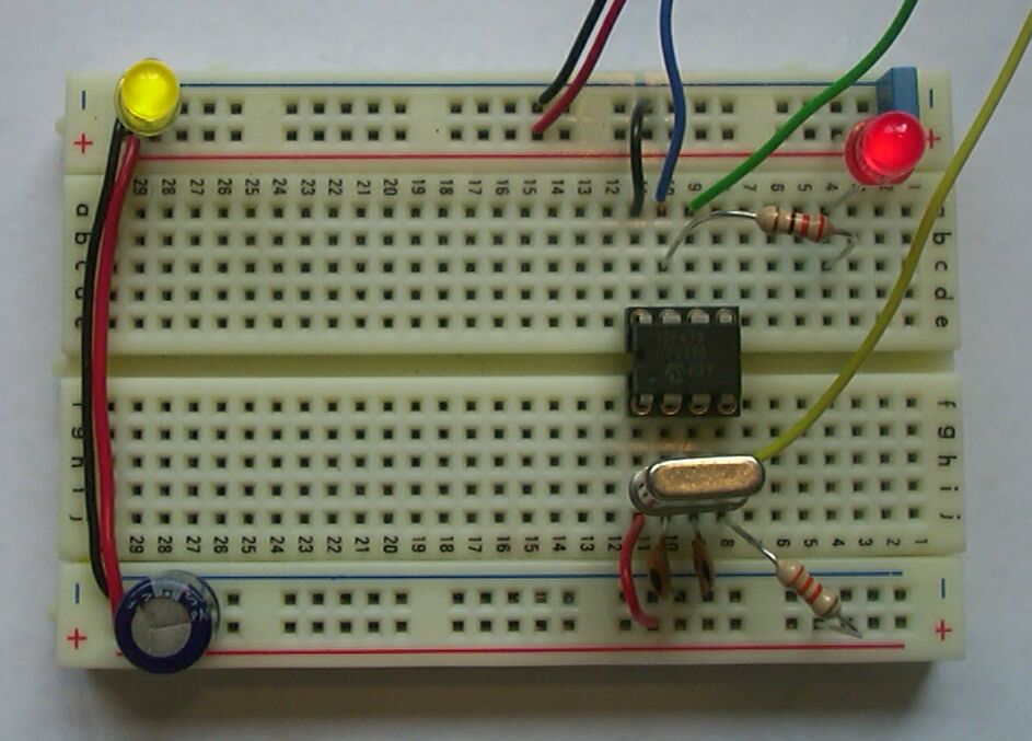
| source | b675-1.jal, b675-2.jal |
| xwisp command line | python xwisp.py go b675-1.hex (or go b675-2.hex) |
The 12F629 and 12F675 are currently the only 8-pin flash PICmicro chips available. The price of these chips makes them very attractive for small projects. These chips do not support LVP, so pin 6 of the target connector (white wire) can be left unconnected.
12F629, 12F675
with internal oscillator and internal /MCLR
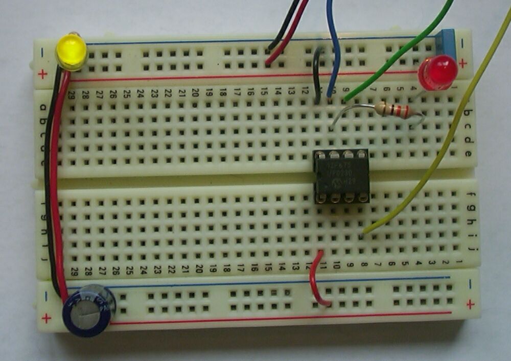
| source | b675i-1.jal, b675i-2.jal |
| xwisp command line | python xwisp.py go b675i-1.hex (or go b675i-2.hex) |
The 12F chips have an internal 4 Mhz oscillator and can be configured for internal /MCLR, which reduces the number of external components, and makes more pins available for I/O (with internal oscillator and internal /MCLR 6 I/O pins are available). Note that the internal 4 MHz clock is sufficiently accurate for blinking a LED, but just barely adequate for reliable asynchronous serial communication.
16F630, 16F676
with crystal
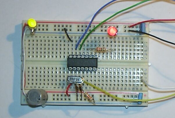
| source | b630-1.jal, b630-2.jal |
| xwisp command line | python xwisp.py go b630-1.hex (or go b630-2.hex) |
The 16F630 and 16F676 are currently the only 14-pin flash PICmicro chips available. The price of these chips makes them very attractive for small projects, that need some more I/O pins that provided by the 8-pin chips. These chips do not support LVP, so pin 6 of the target connector (white wire) can be left unconnected. Note that (unlike other chips) the 16F630 and 16F676 use RA0 as one of the programming pins. Hence the circuits connect the LED to pin RC0. The programs blink both RC0 and RA0, but connecting a LED to RA0 will make in-circuit programming with Wisp628 impossible because the load is too high for the programmer.
16F630, 16F676
with internal oscillator and internal /MCLR
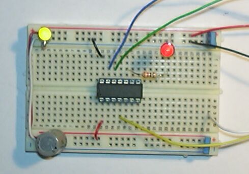
| source | b630i-1.jal, b630i-2.jal |
| xwisp command line | python xwisp.py go b630i-1.hex (or go b630i-2.hex) |
The 16F630 and 16F676 chips have an internal 4 Mhz oscillator and can be configured for internal /MCLR, which reduces the number of external components, and makes some more pins available for I/O. Note that the internal 4 MHz clock is sufficiently accurate for blinking a LED, but just barely adequate for reliable asynchronous serial communication.
16C84, 16F84
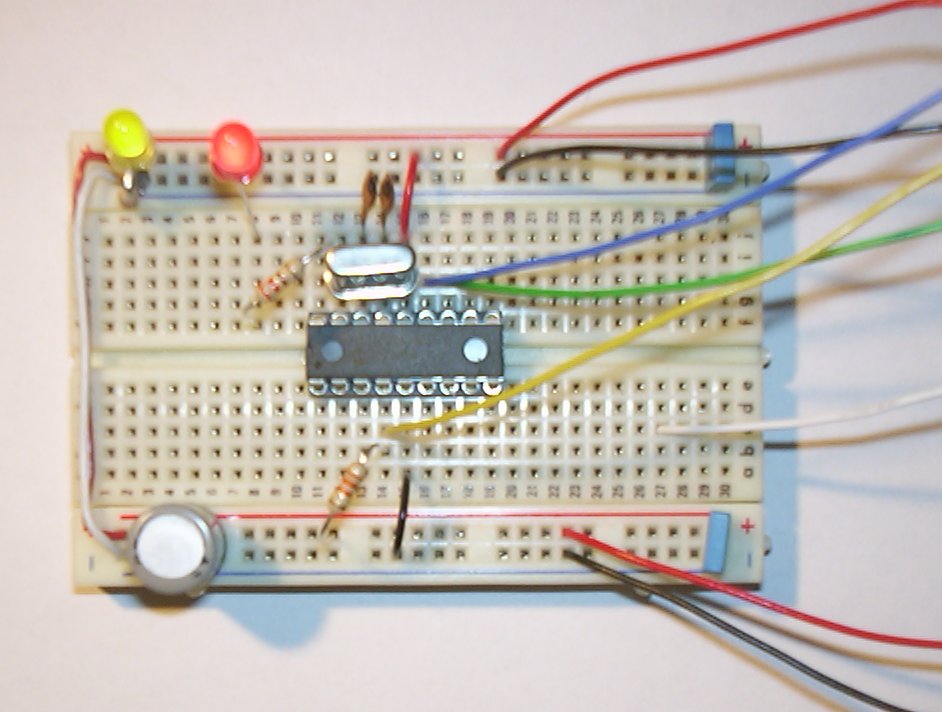
| source | b84-1.jal, b84-2.jal |
| xwisp command line | python xwisp.py target C84 go b84-1.hex (or go b84-2.hex) |
The 16C84 and 16F84 are obsolete (and no longer produced by Microchip), but can still be found in published designs. Unlike the other supported PICmicro's these chips have a maximum clock frequency of 10 Mhz. These chips do not support LVP, so pin 6 of the target connector (white wire) can be left unconnected.
16F84A
| source | b84a-1.jal b84a-2.jal |
| xwisp command line | python xwisp.py target f84a go b84a-1.hex (or go b84a-2.hex) |
The 16F84A is still produced, but for new designs it obsoleted by the cheaper and more powerfull 16F628. Unlike the 16C84 and the plain 16F84 (without the 'a') the maximum clock frequency is 20 MHz. This chip does not support LVP, so pin 6 of the target connector (white wire) can be left unconnected.
16F627, 16F628,
16F818, 16F819,
16F87, 16F88
with crystal

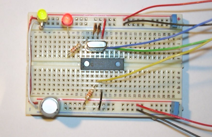
| for 16F62x | source | b628-1.jal b628-2.jal |
| xwisp command line | python xwisp.py go b628-1.hex (or go b628-2.hex) | |
| for 16F81x, 16F8x | source | b818-1.jal b818-2.jal |
| xwisp command line | python xwisp.py go b818-1.hex (or go b818-2.hex) |
The 16F628 is the cheapest 18-pin flash PICmicro (disregarding the 16F627, which has half the code size but is only marginally cheaper - in fact it is sometimes more expensive). The 16F818 and 16F819 are 18-pins chips with A/D converter (which the 16F62x do not have), but without the UART (which the 16F62x do have).
16F627, 16F628,
16F818, 16F819 ,
16F87, 16F88
with internal OSC and /MCLR
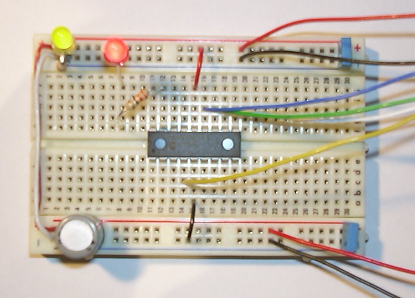
| for 16F62x | source | b628i-1.jal b628i-2.jal |
| xwisp command line | python xwisp.py go b628i-1.hex (or go b628i-2.hex) | |
| for 16F81x, 16F8x | source | b818i-1.jal b818i-2.jal |
| xwisp command line | python xwisp.py go b818i-1.hex (or go b818i-2.hex) |
The 16F62x and 16F81x have an internal oscillator (4 MHz fixed for the 16F62x, 32 kHz .. 8 MHz configurable for the 16F81x) and can be configured for internal /MCLR, which reduces the number of external components, and makes more pins available for I/O. Note that the internal 4 MHz clock is sufficiently accurate for blinking a LED, but not for reliable asynchronous serial communication.
18F1220, 18F1320
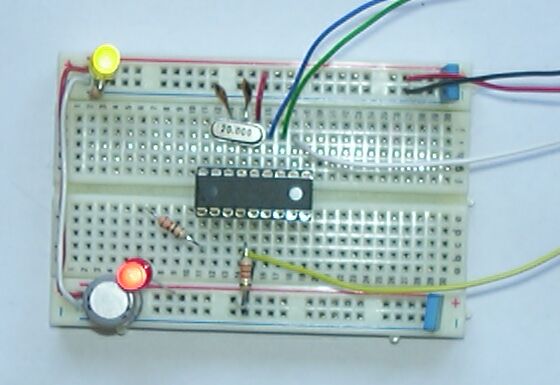
| source | b452-1.jal b452-2.jal |
| xwisp command line | python xwisp.py go b452-1.hex (or go b452-2.hex) |
The 18F1220 and 18F1320 are the smallest (and cheapest) members of the 18F family. These are 18-pins chips, but the pinout differs subtly from the 18-pins chips in the 16F family. The blink code is the same as for the bigger 18Fxxx chips. These chips can also run on an internal clock.
16F73, 16F76
16F870, 16F872, 16F873(A), 16F876(A)
18F242, 18F248, 18F252, 18F258
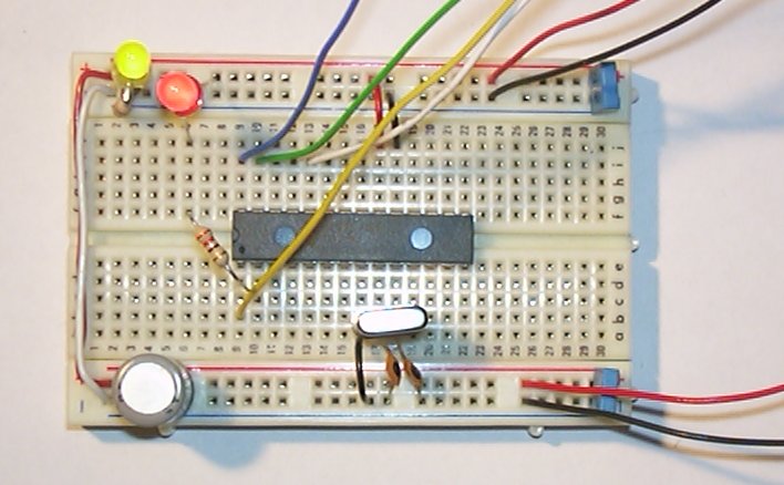
| for 16F7x | source | b77-1.jal b77-2.jal |
| xwisp command line | python xwisp.py go b77-1.hex (or go b77-2.hex) | |
| for 16F87x(A) | source | b877-1.jal b877-2.jal |
| xwisp command line | python xwisp.py go b877-1.hex (or go b877-2.hex) | |
| for 18F2xx(A) | source | b452-1.jal b452-2.jal |
| xwisp command line | python xwisp.py go b452-1.hex (or go b452-2.hex) |
These 28-pin chips can all be regarded as cheaper, stripped-down 16F877(A)'s or 18F2xx's. The blink program for the 16F87x (with or without the A) chips is the same as for the 16F877 itself, for the 16F7x and the 18F25x the program is slightly different.
Note for 18F2xx: the LVP wire (white) must be connected to RB5 instead of RB3 (for the breadboard: next to the purple (used to be green) wire).
16F74, 16F77
16F871, 16F874(A), 16F877
18F442, 18F448, 18F452, 18F458
18F4320
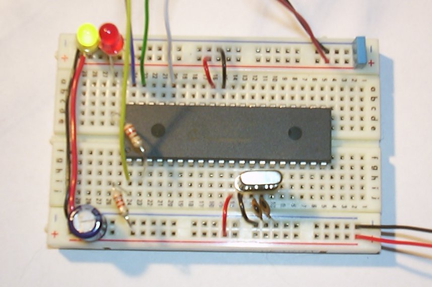
| for 16F7x | source | b77-1.jal b77-2.jal |
| xwisp command line | python xwisp.py go b77-1.hex (or go b77-2.hex) | |
| for 16F87x(A) | source | b877-1.jal b877-2.jal |
| xwisp command line | python xwisp.py go b877-1.hex (or go b877-2.hex) | |
| for 18Fxxx(x) | source | b452-1.jal b452-2.jal |
| xwisp command line | python xwisp.py go b452-1.hex (or go b452-2.hex) |
The blink program for the other 40-pin 16F87x chips (with or without the A) is the same as for the 16F877 itself, for the 16F7x and the 18Fxxx(x) the program is slightly different.
Note for 18Fxxx(x): the LVP wire (white) must be connected to RB5 instead of RB3 (for the breadboard: next to the purple (used to be green) wire).
16F877 asynchronous serial communication
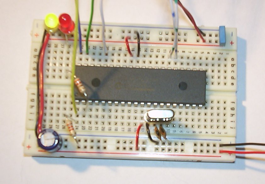
| source | a877.jal |
| xwisp command line | python xwisp.py go a877.hex tty 1200 |
This program repeatedly sends "hello world\n" using asynchronous serial communiacation at 1200 baud, 8 data bits, no parity, 1 stop bit. Pin B7 is used as output, (using true polarity) so Wisp628's passthrough feature can be used to show the message.
| source | a877-b6t.jal |
| xwisp command line | python xwisp.py go a877-b6t.hex tty 1200 |
This program waits for an asynchronous serial character, and the echoes the character, and the hexadecimal and binary value of the character. Again Pin B7 is used as output, (using true polarity) so Wisp628's default passthrough feature can be used to show the message. For inverted polarity (for use with a max232) use a877-b6i.jal or a877-b6i.hex
| source | a877-c6i.jal |
| xwisp command line | python xwisp.py go a877-c6i.hex tty auxi 1200 |
This program is like the previous one, but it uses the UART pin C6 as output, using inverted polarity (like the UART does, for use with a MAX232 or another inverting driver).
Dwarf Boards - the clever microcontroller building blocks
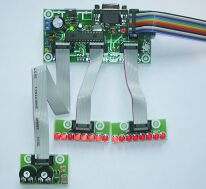 | 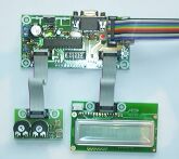 |
This page, including all linked documents and other files, is available as a single zip archive.
introduction
Dwarf Boards is a set of boards that can be combined in very flexible way to create the hardware for your project. Dwarf Boards are cheaper and more flexible than evaluation boards, and much easier than building custom hardware.
documentation
The documentation is in Adobe PDF format. Reader software can be downloaded from Adobe's website at http://www.adobe.com.
descriptions of the available Dwarf Boards
| DB001.pdf | 40-pin controller board | ||
| DB009.pdf | 8 small LEDs | ||
| DB010.pdf | 8 LEDs 5 mm | ||
| DB011.pdf | analog inputs: potentiometers, LM35, LDR | ||
| DB012.pdf | pusbutton and DIP switches | ||
| DB013.pdf | one seven segment display | ||
| DB014.pdf | 8 + 3 solder connections | ||
| DB016.pdf | 28-pin controller board with power and ZPL | ||
| DB017.pdf | LCD interface |
Dwarf Notes
| DN001.pdf | introduction, overview and reference | |||
| DN002.pdf | dbjal.zip | Jal library | ||
| DN003.pdf | source hex | Blink a LED in Jal on DB016 | ||
| DN004.pdf | source hex | kitt-style display in Jal on 22 pins of DB016 | ||
| DN005.pdf | source hex | copy BUS_B to BUS_C in Jal on DB016 | ||
| DN006.pdf | source hex | simple analog input in Jal on DB016 | ||
| DN007.pdf | source hex | count on a seven segment display in Jal on DB016 | ||
| DN008.pdf | source hex | 'hello world' in Jal on an LCD on DB016 | ||
| DN009.pdf | source hex | read 5 analog inputs, show on LCD, in Jal on DB016 |
development tools
The Jal compiler used for the Dwarf Notes is a modified version of the compiler available from SourceForge. These modifications will be fed back to the SourceForge effort. Both the pre-compiled distribution and the source for of the compiler are available.
| jal.zip | Jal compiler distribution for Dwarf Boards (includes the dwarf board specific library files) | ||
| jalsrc.zip | Jal compiler sources |
The DB016 has on-board hardware for the Zero Pin Loader (ZPL) bootloader for 18Fxxx chips. All information about ZPL is available as archive. Note that the use of the ZPL PC software requires a the installation of a Python interpreter, and on Windows also the Win32All extensions. Both can be obtained from www.python.org.
| zpl.zip | ZPL archive |
28-06-2004 There is a bug in the PCB of the DB001 (up to version 1.04): the ICD2 jack connector is connected backwards. See the DB001 document for details.
Workshop
Op 1 mei zal ik een workshop houden in samenwerking met de HCC robotica gebruikers groep. De doelgroep is beginnende PIC gebruikers, die willen leren programmeren in Jal. Voor meer informatie zie de HCCR site.
De deelnemers dienen zelf te zorgen voor: een PC (een laptop lijkt me handig) met een seriele poort (of bv een geschikte USB-naar-serieel converter), met geschikte software (zie hieronder) al geinstalleerd, en verder een knip-, strip- en buigtang voor het knutselwerk.
De PIC en bijkomende hardware kan je naar keuze
- kopen (prijzen zie hieronder), of
- huren (E 5.00), of
- zelf meenemen
Deze hardware die gebruikt wordt met de (koop) prijs:
- een DB016 bord met een PIC18F252 met ZPL bootloader (bouwpakket E 30.00, gebouwd E 42.00)
- een stekkervoeding en een seriele kabel (E 3.50)
- een solderless breadboard (prikbord) (E 9.00)
- een pakketje met wat losse onderdelen (E 8.00): 8 LEDs, 8 weerstanden 470, 2 weerstanden 10k, een druksschakelaar, een pulsgever, een 2x16 LCD, 4 instelpotmeters 10k
De bovenstaande prijzen gelden (alleen) op de workshop zelf.
Voor de training wordt uitgegaan van de bovenstaande hardware. Wil je graag andere hardware (een andere PIC, een programmer, etc) gebruiken dan kan dat, maar de uitleg zal zich richten op de bovenstaande combinatie.
Je hebt natuurlijk een text editor nodig om de programma text aan te maken. Vrijwel iedere text editor is geschikt, zelfs het al in windows aanwezige notepad. Zelf gebruik ik graag UltraEdit of PFE.
Als compiler wordt Jal gebruikt:
- Jal (bv versie 4.59 voor Windows)
Jal installeer je door gewoon de ZIP uit te pakken naar bv C:\. Daarna kan je voor het gemak 'jal-0.4.59.win32' veranderen in 'jal'.
De PC bootloader software maakt gebruik van Python, dus dat moet geinstalleerd worden:
- Python (bv versie 2.3.3 voor Windows)
- voor Windows: de bijpassende win32all, (bv deze voor Python 2.3.3)
Moderne Linux versie zijn doorgaans voorzien van een Python interpreter.
Vervolgens moet je de PC bootloader software installeren (sorry voor de nogal omvangrijke download).
In de workshop zullen (voor zover de tijd het toelaat) de volgende onderwerpen aan bod komen:
- het knipperen van een LED
- het aansturen van een LCD
- het inlezen van een schakelaar
- het inlezen van de A/D converter
- het inlezen van een pulsgever (rotary encoder)
- het combineren van meerdere activiteiten in 1 programma
TOOLS
To use a PICmicro controller you will need at least two tools:
A compiler or assembler to translate your application source code to the standard (.hex) format that can be downloaded to the chip. The Jal compiler is such a tool. |
A programmer (or another way) to download the .hex file into the chip. Wisp628 is a programmer. WLoader is a so-called bootloader (a program, running in the PICmicro itself, that communicates with your PC, accepts an .hex file and loads it in the - remaining - memory of the chip). XWisp is a windows program that handles the communication with Wisp, Wisp628 or WLoader. The Wisp tool is a (older) DOS/Windows command line that serves the same function |