Fonte:
Wouter van OoijenYou can buy a Wisp628 kit, or buy a 16f628 with Wisp628 firmware, or use this description to build your own programmer. No hidden costs, the PC software and firmware upgrades are free.
Features
| |  | takes power from the target circuit |
|  |
Foremost Wisp628 is an in-circuit programmer. The programmer is connected to a few pins of the target PICmicro, which is programmed while it remains in the circuit. The target circuit must be compatible with the programmer to make this in-circuit programming possible.
Wisp628 is designed to be used as an in-circuit programmer only, hence no socket is provided for the target chip. 'Why use such a limited design', you might ask, 'an ex-circuit programmer with a ZIF socket can do the same things and more!' You are partially right, but consider the way you would use and ex-circuit programmer for development: take the chip from its circuit, put it in the programmer, program it, take it from the programmer, put it in its circuit, test. Of course, you can do that, no problem. But think of how many times you will have to do that before your program is working satisfactory, and how many chip pins you will break in the process. Now compare that to in-circuit programming: you will have to spend some time to prepare the circuit for in-circuit programming, and to make the right connections (but this can be as easy as clipping a DIL clip onto the target chip!). But after this has been done you can sit behind your PC and code, compiler, program (download) and debug, without touching the target circuit. Believe me, after working this way once you will regret going back!
Wisp628 is a High Voltage Programming (HVP) programmer: it applies 13 Volt to the /MCLR pin of the target PICmirco to put it in programming mode. Wisp628 uses a charge pump to create this voltage, so it can not provide much current. This is OK for flash PICmicro's (which use the voltage only to enable programming), but not for EPROM chips (which use the 13 Volt to power the actual programming, requiring substantial current).
The following target chips are currently supported : | | | 12F629, 12F675 |
| | | 16F627(A), 16F628(A) |
| | | 16F630, 16F648A, 16F676 |
| | | 16F72, 16F73, 16F74, 16F76, 16F77 |
| | | [16F737, 16F747, 16F767, 16F777] |
| | | 16F818, 16F819 |
| | | [16F83], 16C84, 16F84(A) |
| | | 16F870, 16F871, 16F872, 16F873(A), 16F874(A), 16F876(A), 16F877(A) |
| | | [16F87], 16F88 |
| | | 18F1220, 18F1320, 18F2220, [18F2320] |
| | | 18F242, [18F2439], 18F248, 18F252, [18F2539], 18F258 |
| | | 18F4220, 18F4320 |
| | | 18F442, 18F4439, 18F448, 18F452, [18F4539], 18F458 |
| | | [18F6520, 18F6525, 18F6585, 18F6620, 18F6720] |
| | | [18F8520, 18F8525, 18F8585, 18F8620, 18F8621, 1F8680, 18F8720] |
| |  |
notes:
| | | writing ID memory is not supported for 16F7x |
| | | chips that are shown in square brackets are supported conform Microchip's programming specifications, but have have not been tested with a real chip |
| | | although not explicitly mentioned the LF (low power) variants of the mentioned chips are also supported |
| | | programming chips that can configure their /MCLR pin as input can (especially when this feature is used) requires an additional circuit |
| | | A special note for the 18FXX39 chips: these chips have the same on-chip identification code as the (very similar) 18FXX2 chips. when you want to read the image of an 18FXX39 be sure to specify the target chip explicitly to the programmer softeware, otherwise the full 18FXX2 address range will be read, instead of the slightly smaller 18FXX39 address range, which would cause a verification error when you later try to write such an image to an 18FXX39 chip. |
Wisp628 supports a rapid development cycle: without even touching the target hardware you can program the target, reset the chip, start the programmed application, and even communicate with it.
Microchip (the manufacturer of the PICmicro chips) makes a distinction between production programmers, which verify the programming at the extremes of the Vcc levels that are to be expected in the target circuit, and prototype programmers, which verify at one Vcc level only. Wisp628 derives its power from the target circuit, hence it is a prototype programmer. Note that you can use Wisp628 for occasional production-grade programming, but then you must vary the Vcc of the whole circuit (including Wisp628), for instance by using a variable power supply.
Wisp628 takes its power from the target circuit, which must provide a stable 5V @ 20mA (4.5 .. 5.5 Volt will work). The PICmicro in the Wisp628 can run on a lower voltage, but then the charge pump might not be able to generate a voltage that is high enough to put the target in programming mode.
Wisp628 uses a serial interface with a simple yet robust protocol. Neither the timing of the communication nor the RS-232 levels produced by the PC will affect the programming. Wisp628 iteself produces a true RS-232 level signal.
The PC-to-programmer connection requires a 9-pin serial extension cable (male at one side, female at the other side, straight connections, hence not a null-modem cable).
Wisp628 provides a serial passthrough which is usefull when you want to communicate with your target system. The same serial line that is connected to the Wisp628 programmer can be passed on to the target PICmicro's pins RB6 + RB7 (the ones that are already used for programming), or - using additional wires from Wisp628 to the target PICmicro - any pair of pins (most likely: the pins that are connected to the targets build-in UART). The passthrough is implemented in software, so it is best used with baudrates of 19k2 and lower. The passthrough can handle both inverted and non-inverted signal levels at the target PICmicro side.
Wisp628 is derived from the older WISP (16x84 based) design, but replaces the obsolete 16x84 with the newer (and cheaper) 16F628.
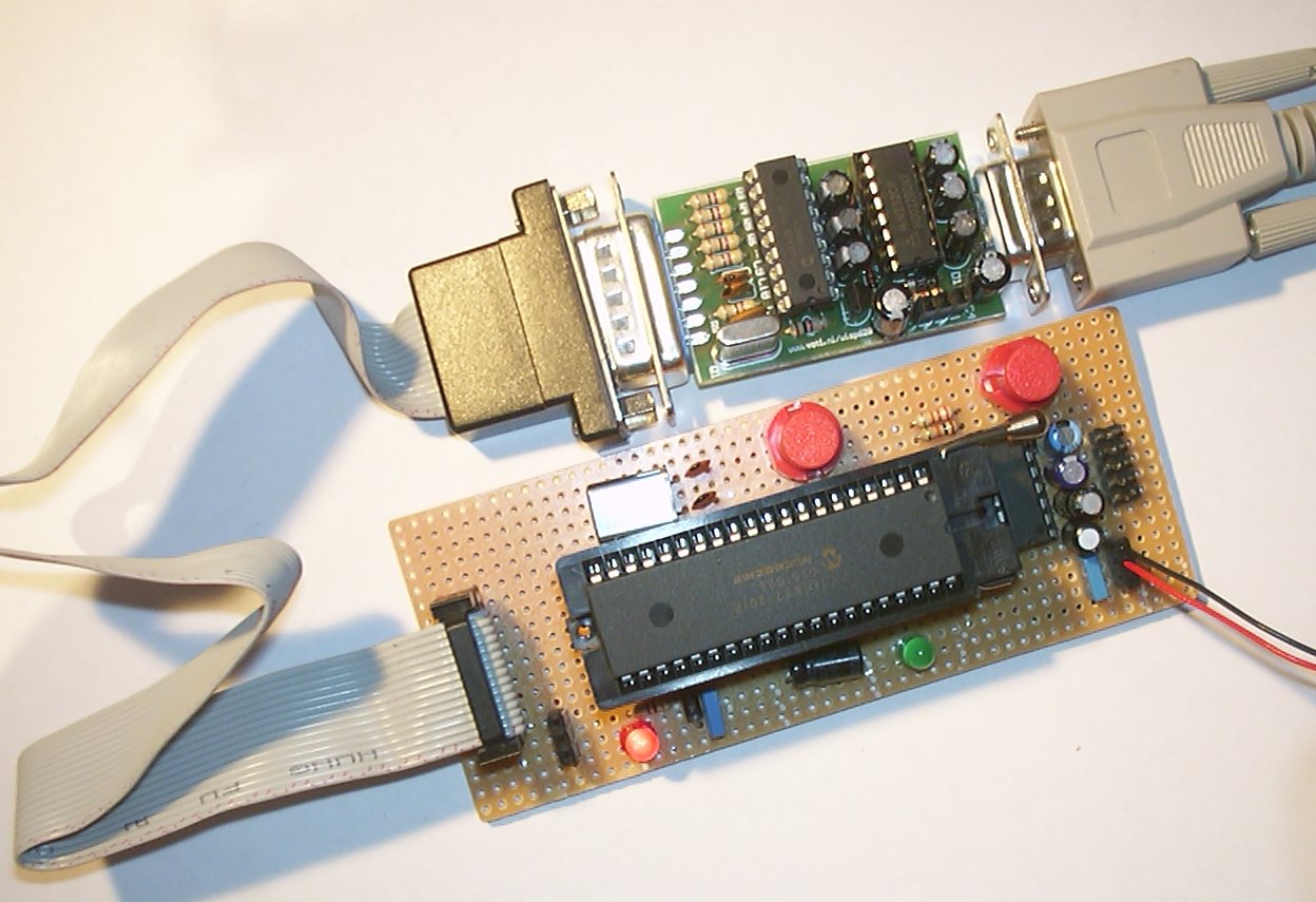
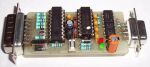
Circuit
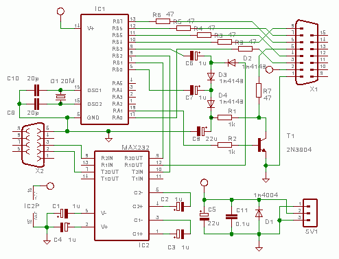
The Wisp628 circuit consists of
| | | a charge pump that creates the 13V programming enable voltage (D2..D4, C6..C8) and a transistor to switch this voltage (R1, R2, T1) |
The circuit shows a 3-pin header that can be used to provide power to the programmer (and via the programmer to the target circuit) when the target circuit itself does not provide power. Note that the outer pins are both ground, so it does not matter how you plug the connector in.
A MAX232 (or equivalent) connverts between the TTL levels at the PIC pins and the RS232 levels at the PC side. Only two RS-232 lines (RX and TX) are used.
While programminging the charge pump is active. It produces a Vpp (programming enable voltage) of 3 times Vcc (5 Volt) minus 3 diode drops. Transistor T1 is used to switch the Vpp. Capacitor C8 bridges short periods in which the PICmicro does not cycle the charge pump. Note that the source of the charge pump is not Vcc but a pin of IC2 (which is at or near Vcc level). This was done to make it easier for me to design a PCB. Feel free to connect D2 to Vcc instead.
T1 is specified as a 2n3904, which a very cheap American transistor, but sometimes not readily available in other countries. Feel free to substitute another small-signal transistor (in an early version I used a bc547).
The PICmicro uses a standard 20MHz Xtal with accompanying capacitors. The 16F628 is configured for internal reset, so /MCLR is not connected.
The target connector is a D15M connector. Only the 'top' row of 8 pins is used. This makes it possible to use a solder cup connector fitted in 'card edge' style. All lines to the target (except Gnd and Vcc) have 470 ohm series resistor to damp line reflections and to offer some protection against wrong connections (the circuit diagram shows 47 ohm, which is OK too).
The target connector provides
| | | Gnd and Vcc (remember that Wisp628 takes its power from the target circuit) |
| | | the three programming lines (to be connected to RB6, RB7 and /MCLR of the target) |
| | | an optional fourth programming line that pulls the LVP enable pin of the target PICmicro down |
| | | two more optional 'programming' lines that can be used to communicate with the target |
When you make a PCB or otherwise build your Wisp628 remember that
| | | C11 should be as close to the Gnd and Vcc pins of the 16F628 as possible |
| | | the leads from the 16F628 to C9, C10 and Q1 should be short |
| | | the earthed side of C9 and C10 should connect directly to the Gnd pin of the 16F628 |
Additional circuit
The Wisp628 circuit as described above is designed to apply Vpp (the programming enable voltage) to the /MCLR pin while Vcc (power) to the target PIC is active. Some newer PICs can configure their /MCLR pin as input. These chips will (in most cases) fail to get into programming mode with the standard Wisp628 circuit when the /MCLR pin is indeed configured as input. The circuit below can be inserted between the Wisp628 and the target PIC to solve this problem. Its main function is to short the target PICs power very briefly (a few milliseconds). The diode ensures that the Wisp628 still has power during this brief period. In some cases it might be necesarry to add a bigger elco on the Wisp628 Gnd and Vcc pins (1000 uF or more), or use separate +5 Volt power supplies for the target and for the Wisp628 programmer. In any case the power to the target PIC must tolerate the brief short, it must not deliver more current than the TIP120 can handle (a few Ampere), and it must recover fast. A 7805 or 78L05 based power supply will do fine, some lab power supplies will not, because they are designed to 'fold back' after an overcurrent situation and recover slowly. In such cases a 10 Ohm resistor in series with the ppwer supply might solve the problem.
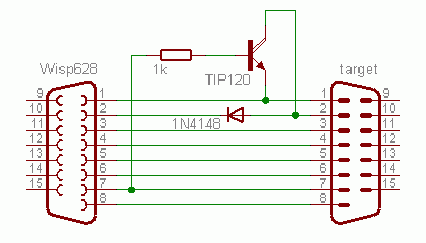
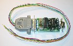
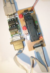
Note that the additional circuit might make the programming of some older PICs impossible, and using the serial passthrough with the 'extra' pins will inadvertently enable the circuit, so it might be a good idea to make the circuit removeable. The picture below shows a 'dongle' style implementation that can be fitted (or not) as needed.
Target circuit and connection
The table below shows how the Wisp628 programmer must be connected to a target PICmicro controller.
| D15 pin | target connection | recommended
wire color | 8-pin PICmicro's | 18-pin PICmicro's | 28-pin PICmicro's | 40-pin PICmicro's |
| 12F629 12F675 | 16C84 16F84(A) 16F627 16F628 | 16F73 16F76 16F870 16F872 16F873 16F873A 16F876 16F876A 18F242 18F248 18F252 18F258 | 16F74 16F77 16F871 16F874 16F874A 16F877 18F442 18F448 18F452 18F458 |
| 1 | Gnd
(ground, VSS) | black | 8 | 5 | 8, 19 | 12, 31 |
| 2 | Vcc
(power, VDD) | red | 1 | 14 | 20 | 11, 32 |
| 3 | RB6 | green | 6 | 12 | 27 | 39 |
| 4 | RB7 | blue | 7 | 13 | 28 | 40 |
| 5 | /MCLR | yellow | 4 | 4 | 1 | 1 |
| 6 | LVP (PGM) | white | - | 10 | 24 | 36 |
| 7 | asynch Wisp628 ==> target | - | 7 | 18 | 26 |
| 8 | asynch Wisp628 <== target | - | 8 | 17 | 25 |
Notes:
| | | The pin numbers show are for the DIP packages. |
| | | The 40-pin chips have two pairs of ground and power pins, the 28-pin chips have two ground pins. Your target circuit should connect all ground and power pins. It does not matter to which ones the programmer is connected. |
| | | The LVP line is not used for PIC 16x84's, and can (for other targets) be left unconnected when the target cicruit pulls the LVP (PGM) pin down. |
| | | D15 pin 7 and 8 connections are optional. These pins can be left unconnected, or can be connected any way you see fit for serial passtrough. The indicated pins are the ones that match the target's build-in UART (note that the 12Fxxx and 16x84(A) chips have no UART). |
 |  |  |
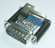
| When the target circuit is built on a breaboard the connection between the Wisp628 programmer and the target can be made simply by inserting a few extra wires in the breadboard. | A DIL clip makes connecting to a target chip very easy, and can be used when the chip is already soldered into a PCB. | A game connector salvaged from a PC gamecard can be used to connect the Wisp628 D15M connector to a 2x8 row of pin headers, for a more permanent and robust connection. |
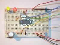
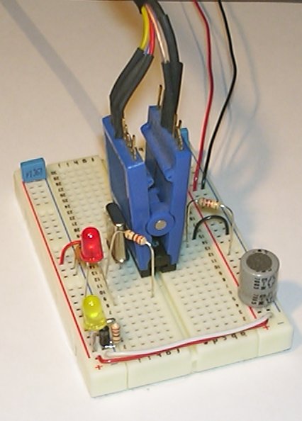
For a first try at using a PICmicro controller it is advisable to use a know working 'blink a LED' program, like I provide on my blink a LED page.
Compatibility
The Wisp628 programmer must be able to drive the /MCLR pin of the target PICmicro via a relatively high impedance, up to the 13 Volt programming voltage. This rules out the use of a capacitor directly tied to /MCLR to time the reset. Wisp628 compatible reset circuits are:
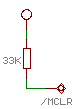 | 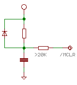 |
| just a 33k to Vdd (might not work when the Vdd switches on slowly) | a split resistor plus capacitor and diode; sum of the two resistors must be <> |
The Wisp628 programmer must be able to drive the RB6, RB7 and (when applicable) LVP pins of the target PICmicro. A simple way to assure that this is possible is to have 10 kΩ resistor between the PICmicro pin and the rest of the circuit (somewhat lower values might also work, YMMV). When the circuits connected to these PIC pins are input-only there is of course no problem, but be aware that for instance the data lines of an HD44780 LCD driver can turn to outputs when the R/W line is left floating (which will, during reset, happen when it is connected to another pin of a target PICmicro).
Software
The XWisp program can be used to control the Wisp628 hardware. This program can be used on Windows (95 or higher), either from a DOS box command line or using the windows interface. It is available as Python source. It requires that a suitable Python (2.1 or higher) and the Python for windows extensions are installed. The XWisp program supports the full range of target chips supported by Wisp628.
The Wisp program is DOS a command-line program that can be used to control the Wisp628 hardware. It is available as source or as executable for DOS/Windows. This program will work only on DOS, or on Windows versions that allow direct access to the serial port hardware. It will not work on NT or NT-derived Windows versions, unless a suitable driver is installed that enables direct access to the serial port hardware. The Wisp program supports only a limited range of target chips:
| | | 16C84, 16F84, 16F84A |
| | | 16F627, 16F628 |
| | | 16F73, 16F74, 16F76, 16F77 |
| | | 16F870, 16F871, 16F872, 16F873, 16F874, 16F876, 16F877 (note: not the A versions) |
Both a description protocol used by Wisp628 (next section), the code for the Wisp628 firmware, and the code for XWisp and wisp.exe are available. This makes it prossible to write your own PC software for Wisp628, which a number of people have done. The ones that I am aware of are (in no particular order). Let me know if there are others.
| | | LINWLOAD intended for WLoader only, but will probably work with Wisp268 (with some limitations) |
Protocol
The firmware uses an ASCII protocol, which adheres to the WBus definition. Some knowledge of the protocol might be needed when you want to port the existing Wisp or XWisp programs, create a new one, or simply want to test your Wisp628 hardware using a terminal emulator. When you just want to use the existing PC software the protocol is of no interest to you.
The protcol description is quite lengthy, so I have put it on a separate page.
FAQ
| | | How can I check that the 16F628 in my Wisp628 is running? | | Connect a LED and suitable series resistor (470 ohm) between Vcc and pin 6 of the DB15 connector (LVP). Make sure the LED is in the right direction (flat side with internal metal 'cup' towards pin 6). The LED should flash two times very quickly when power is applied. |
|
| | | Can I use Wisp628 to program a FLASH PICmicro that is not listed as supported? | | As far as the Wisp628 circuit is concerned you probably can, but the PC software must support the chip. Check the XWisp pages for the latest version. (And feel free to get the source code and extend it! But first check that the chip is actually available, there is a some vapourware on Mirochips website). |
|
| | | Can I use Wisp628 to program EPROM PICs? | | No. The Wisp628 programmer generates the voltage to put the PICmicro in program mode using a charge pump (a few diodes and elco's). This charge pump can not provide sufficient current for EPROM programming. |
|
| | | I have a PICmicro that I want to copy. Can I use Wisp628 to do that? | | Of course, provided that the source PICmirco is not copy protected. Just read the source, write the contents to a .hex file and use that .hex file to program the new chip. But if the source chip is copy protected you are out of luck (and you probably have no business copying it anyway). |
|
| | | Can I use Wisp628 for LVP programming? | | No. But why would you want to? Wisp628 uses HVP programming, which can do everything that can be done with LVP programming, plus a bit more (changing the LVP enable fuse bit). |
|
| | | I have quickly build this programmer but it does not work / suddenly my PC has stopped working / the PICmicro chip has let out it's white smoke, and I realy need to program PICs. What should I do? | | Buy the kit, follow the instructions carefully, and next time when you build something don't rush it. Include a 'fools diode' (a 1n400x connected to the power and ground lines) in everything you build. Use an 7805-based power supply, so you can not expose your circuit to more than 5 Volt or more than 1 Ampere. Using a PC power supply is a bad idea, because when you connect it the wrong way round - you will, sooner or later - it can supply enough current to blow the fool's diode first and then kill your PICmicro. When you still want to use a PC power supply I suggest to connect a 5Ω / 5 Watt resistor accross the 5V lines and use the 12V lines as input to an 7805, and use the output of the 7805. |
|
| | | I bought / build your programmer, but now you have come up with a new version of the firmware (code in the 16F628). How can I upgrade my programmer? | | Get yourself a new, blanco 16F628. Get the new wisp628.hex file (see downloads). Program the blanco 16F628 with the new wisp628.hex file. Remove the old 16F628 from the programmer and put the new one in. After verifying that the programmer works (and shows the new firmware version number when you use it) you can recycle the old 16F628 for a project (or keep it, just to be safe). |
|
| | | I double-click on the wisp icon but nothing happens. | | The wisp tool is a DOS command line program, so you must open a DOS box and use it there. |
|
| | | The wisp tool complains about a communication error. | | Check that you are using the right serial port, and (for NT-derived Windows versions) that direct hardware access is enabled. Remove the programmer from the cable, and instead make a connection between pins 2 and 3. Now give the command
python xwisp.py port com2 term 1200
(again replacing com2 with the serial port you intend to use). Now when you type something you should see it. When you don't see your typing the serial port can eiter not be accessed from the DOS box, or it is not the serial port your cable is connected to. |
|
| | | Can you send me a Wisp628 PCB design? | | Sorry, I won't. I sell a kit containing all Wisp628 parts, including a programmed 16F628 and a PCB. I want to encourage Do It Yourself activities, but you will have to use a breadboard, or design your own PCB. If you want the comfort of an existing PCB: buy the kit! |
|
Legal notes
The information (circuit design, description, code) for this design is copyrighted. The right to use this information is granted to everyone, on the condition that it is not used to sell Wisp628 programmers, kits, PCBs or programmed PICmicro's for such programmers.
Some borderline cases:
| | | It is allowed to design and make a Wisp628 PCB, but it is not allowed to have it made for you by a PCB company, nor is it allowed to sell such a PCB, or to provide the PCB design to the general public. |
| | | It is allowed to program a 16F628 with the Wisp628 firmware, create a PCB, or even build a complete Wisp628 programmer for a friend, als long as you do not make any money doing so. |
Note that there is no restriction on the use of a Wisp628 programmer.
Why these restrictions? Because I must make a living, and I would like my PICmicro activities to contribute to that, so I can justify spending more time on this activities. That includes updating the Wisp628 design and PC software for it, so in the end you would benefit too.
Downloads
Besides the web page you are looking at now the following is available:
| | | the firmware hex file for a 20 MHz 16F628 (version 1.0)
|
| | | the circuit in EAGLE format (gzip'ed) |
| | | the Wisp and XWisp programs are available from their respective pages |
| | | test programs can be found in the hello world section of this page. The Jal compiler used to make these programs has its own page. |
Links
 | Microchip is the manufacturer of the PICmicro chips. The website provides datasheets, application notes and the MPLAB integrated (assembler) development environment. |
 | The piclist is THE source for information about PICs. The website provides links to all kinds of usefull resources, for instance some simple programmers to program the 16F628 in your Wisp628. |
 | CadSoft provide a free version of their circuit and PCB editor. This EAGLE light is limited in board size and number of layers, but very usefull for small projects. The circuit diagram of Wisp628 falls within this limits. You could use it to create a PCB. |
 | On his (Dutch language only) website Frits Kiefenbelt describes a variation of the Wisp628 programmer which he calls Galva-Wisp. His circuit adds optocouplers to achieve galvanic isolation between his PC and the target PIC circuit. Note: one of his projects is a PIC controlled dimmer that connects directly to the mains, so he realy needed this isolation. |