If the piclist is an any indication the 16f877 seems to be the new favorite hobby microcontroller, a position that used to be occupied by the 16f84/16c84. Compared to is older brethren the 16f877 has much more to offer at around twice the price. As for all Microchip controllers the datasheet (pdf) and the MPLAB assembler IDE are available for free. (Microchip keeps changing its website, so when these links turn out to be invalid you might have to look around a little.)
The 16f877 supports three methods to get a program into the chip:
- HVP (High Voltage Programming) uses 12-14V on the reset (MCLR) pin to enable the serial programming mode via pins B6 and B7.
- LVP (Low Voltage Programming) uses B3 as (TTL level) enable input for the same serial programming mode.
- Self-programming uses a program executed by the 16f877 itself. This is the approach used by loader firmware.
HVP is always available. This is the programming method common to all PIC chips. LVP seems to be available on all new flash chips (16f87x, 16f62x). Self-programming is unique to the 16f877 and its close relatives (16f87x). LVP is available only when it is enabled by a bit in the fuses word (which can only be changed using HVP). LVP claims pin B3 as enable pin. By default a 16f877 is delivered with LVP enabled. (Loading the WLoader firmware disables it, so B3 is freed for use by the application.) Self-programming means that the 16f87x can program its own code FPROM, so - once you have loaded suitable application loader firmware in your target 16f87x - a simple serial interface to your PC is all you need to download and run an application. The pro's and con's of the three loading methods are summarized below.
| Method | Pro | Con | Comment |
| HVP | can be used with all PICs no dedicated pins | needs 12-14V to enable, so programmer hardware is a bit complicated | best (only?) choice for production work |
| LVP | does not need 12-14V to enable, so only simple (TTL-only) hardware is needed can program fuses word (but not LVP enable) | pin RB3 is dedicated to program-enable can not change LVP enable bit can be used with newer flash PICs only (16F87X, 16F62X) | good choice for a very simple parallel port programmer |
| self-programming (bootloader) | activation method can be choosen freely communication method can be choosen freely | can not program fuses word can not be combined with code read-protection can be used with 16F87X PICs only the bootloader reduces the amount of code flash available for the application some compilers are not compatible with (some) bootloaders | good choice for a simple serial port-based loader |
WLoader is yet another loader hardware / firmware / PC software set, but one that - in my opinion - has a very good set of features:
- either a true RS-232 level interface using a MAX232 (recommended), or a el-cheapo pseudo RS-232 serial interface, using only a few passive components (cheap, but for the brave ones only!)
- the serial interface use only one I/O pin
- the serial interface does not use the UART, so it can be assembled for any pin (except for the open-drain A4), and it can use non-inverting RS-232 hardware
- the serial interface pin can be re-used for most output purposes
- intelligent handling of application code that starts at 0000
- intelligent handling of the configuration fuses word
- protocol and DOS command line interface compatible with the Wisp programmer (e.g. load-verify-run-debug with one command line)
- protocol, firmware, DOS software and schematics are free
- occupies top 1K of the 8K code flash, so lower 7K is available for the application
- Rick Farmer's PICLOADER
- the HiTech loader
- Tony Nixton's ROMzap (his site has disappeared, does anyone kwow where to get his stuff?)
- Shane Tolmie's PIC16F87x and other bootloaders
- Karl Lunt's PIC bootloader
If neither WLoader nor any of the other bootloaders satisfies your particular needs (for instance because you want I2C, SPI or another exotic interface) do not hesitate to develop your own bootloader, it is not very difficult. Feel free to ask my assistance for such a project, but I will have to charge you a commercial rate - beside my hobbies I must make a living!
The block diagram shows the taget circuit as far as relevant for WLoader. The WLoader specific parts are a RS-232 send/receive combiner (a nice term for a few resistors), the RS-232 interface, and a remote reset circuit. The remote reset circuit can be omitted when the target circuit already has a manual reset (pushbutton switch), but it is very convenient to be able to reset the target (and hence activate WLoader) from the PC.
The block diagram also suggests how the circuits can be divided between the target itself and a download dongle. A production system could just provide the relevant signals on a 2x4 pin header, and rely on a download dongle that contains the remote reset and the RS-232 circuitry.
Note the resistor on the (single) line from the PIC used for communication. This resistor determines the level on the line when either the rest of the circuit or the PC is not connected, so in that case the application is started automatically when the PIC is reset.
The preferred version of the WLoader hardware uses a MAX232 for RS-232 level conversion.
The right side of the circuit shows a fairly standard 16F877 target with reset (R5, R6, S1), power decoupling with reverse polarity protection diode (C1, D4), a 20 MHz crystal (Q1, C2, C3) and a LED (R4, D3). Note that conform good practice both sets of power pins of the 16F877 are connected. Except for the crystal (which must be 20 MHz) and the reset (see below) you can vary this part of the target circuit to suit your needs, or use what you already have in your design.
The WLoader specific stuff consists of a D9F connector and MAX232 level-converter (X1, IC2, C4..C7). The send-receive combiner is just R3. R1 is needed when the MAX232 can be removed from the circuit (when it is part of a download dongle) to provide a low level on the RE2 pin of the 16F877, so WLoader will start the application. R2 is needed when the MAX232 is a permanent part of the circuit, again to provide the low level on RE2, in this case when no PC is connected.
Note that the pull-up on the /MCLR pin is split in two (R5, R6) to allow a pull-down by the reset switch without shorting the R2OUT of the MAX232, and to reduce the load on the /MCLR pin when the target is programmed in-circuit.
This 'el-cheapo' version of the WLoader hardware uses a few resistors and a zener diode as RS-232 interface. It is shown here mainly because this was the original WLoader hardware. I recommend this version only to those who are enthousiastic about minimal-hardware solutions and can solve the problems that might occur. Don't ask me for help.
The right side or the circuit is the same 16F877 target circuit as used with the MAX232. The only difference is that the /MCLR pull-up is one resistor.
The RS-232 interface (R2, D1, R7, R3) avoids current through the 16f877 protection diodes, which is outside Microchip's operating specs and is rumored to cause all kinds of nasty effects. When the RS-232 input voltage is positive the D1 zener and R7 / R1 limit the voltage on the interface pin to somewhere between 4.7 V and Vcc. When the RS-232 input is negative the zener (now acting as diode) and the same resistors put a voltage on the interface pin that is close to zero. When nothing is connected to the RS-232 connector R1 keeps the 16f877 input high, which causes the loader to start the application when a reset occurs.
D2, R4, R5 and T1 provide a reset when the corresponding RS-232 line is high.
When the circuit is split between a dongle and the real target R1 must be included in the target so the application will be started on a reset.
The loader interface hardware can be part of the final circuit, and the loader interface pin can be shared with its operational function, but some attention must paid to its use:
- the loader interface pin must be pulled low (for the MAX232 version) or high (for the el-cheapo version) after a reset
- the PC's RS-232 must be able to drive the loader interface pin
- during loading the loader interface pin is driven by the loader firmware.
When the target circuit must be kept as simple as possible the (real or el-cheapo) RS-232 interface, and the remote reset circuit can be put in a download dongle. In this case I recommend to use a 2x4 pin header (one pin removed as key) on the PCB and/or a D15M connector. When the pin assignment shown in the table is used the interface can be used both for HVP programming (Wisp programmer) and self-programming (WLoader).
| Key | Gnd | Mclr | E2 |
| B6 | B7 | Vcc | reserved |
| pin | 1 | 2 | 3 | 4 | 5 | 6 |
| Use | Gnd | Vcc | B6 | B7 | Mclr | E2 |
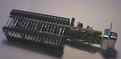 The picture shows how I combined the WLoader hardware (old-style 'el cheapo' version) and a DB9 connector with a 16f877 in a wire-wrap socket, with a normal (round-pin) socket at the end of the wire wrap pins. The whole gadget can be plugged in where a 16f877 would fit and adds in-circuit downloading to a circuit. The 33k reset pull-up and a LED for power indication can be disabled by pulling two pin header jumpers (for low-current tests).
A reset (either manually or via the remote reset circuit) activates the loader. When no PC or download dongle is connected a resistor forces the interface pin to the opposite polarity of what it would be with the PC etc. connected. The loader detects this and will immediately activate the application. When a PC is connected the input is low (the RS-232 idle level is negative) and the loader will wait for instructions from the PC. The Wisp PC command-line tool can be used to download the application code, to verify the downloading, to start the application program, and provides a simple TTY interface that can be used to communicate with the application. The user must disconnect the RS-232 cable when the application program must run automatically after a reset.
The loader puts a goto instruction at addresses 0..2 to activate itself on reset. The user application instructions at these addresses are put at a location within the loader, and are executed before the jump to the rest of the user application program, starting at address 3. Hence the application loaded by the loader can be exactly the same as a stand-alone program downloaded to the 16f877. This trick will fail when the application program tries to use the instructions at the low addresses for something clever like
   $0000 reset_vector:         goto main
   $0001 delay_12:             call $+1
   $0002 delay_8:              call $+1
   $0003 delay_4:              ret
   $0004 interrupt_vector:     ...
Luckily most compilers are not that clever. For an overly-clever compiler you can try to let the application start with three NOPs.
The loader accepts instructions from the PC to write the configuration fuses and the code locations occupied by the loader. It does not actually perform the write, but does verify against the stored value, or in case of the configuration fuses word, against a copy of the actual fuses value. Hence the loading will not be hindered by the configuration fuses in the hex file, and a copy can be made of the application and configuration fuses and this copy can be downloaded using either the loader or a normal programmer. Note that in such a copy the loader will be disabled because the applications code for the addresses 0..2 is read, not the actual jump to the loader.
The protocol adheres to the WBus definition, but the WLoader is always in active mode after a reset of the 16F877, so it does not support multiple devices on the same bus. Hence the break condition and the hello commands are not needed, but do no harm. This discription mentions only the aspects that are specific to WLoader.
The (pseudo) RS-232 interface circuit is self-echoing: everything that the PC sends is also received by the PC, and the 16f877 can only send when the PC is silent.
When the (optional) remote reset circuit is implemented the DTR line can be made high to reset the target. After this is done an appropriate delay must be observed for the target to start.
Besides the standard WBus-defined commands the WLoader firmware implements a number of specific commands which are described in the next table, together with the WLoader-specific aspects of the WBus-defined commands.
| format | name | effect |
|---|---|---|
| 0000G | Go | The application program is started. |
| I | Increment | The current memory location pointer is incremented. |
| abcdL | Lazy write | The hex value abcd is written to the current memory location if and only if the current location differs from abcd. The final W is echoed as W when programming is not necessarry or the programming is succesfull. The L is echoed as ? when programming is necessarry but not succesfull, as L when programming is either not necessarry or succesfull For program and configuration memory the higer two bits (of a) are ignored. For the data memory the higher 8 bits (a and b) are ignored. |
| 0000P | Passthrough | The application program is started. |
| R | Read | The current memory location (4 hexadecimal digits) is read and coped the content to the communication buffer. For program memory the higer two bits are set to 0. For data and configuration the higher 8 bits are set to 0. |
| T | Type | The type name (WLdr) is copied to the communication buffer. |
| V | Version | The version number (4 hex digits) is copied to the communication buffer. The current version (01.00) reads as 0100. |
| abcdW | Write | The hex value abcd is written to the current memory location. The final W is echoed as W when the programming is succesfull. It will echo as ? when the programming is not succesfull. For program and configuration memory the higer two bits (of a) are ignored. For the data memory the higher 8 bits (a and b) are ignored. |
| CX | Code | The programming / readout mode is activated for the program memory. The current location is set to the first location of the program memory. |
| DX | Data | The programming / readout is activated for the data memory. The current location is set to the first location of the data memory. |
| EX | Erase | No operation (maintained for compatibility with WISP hardware). |
| FX | Fuses | The programming / readout mode is entered for the configuration memory. The current location is set to the first location of the configuration memory. |
The I, L, R and W commands make sense only in one of the programming / readout modes.
example
It is the responsibility of the host to issue the correct sequence of commands to program the target and (if required) to start the target. A typical program - run sequence would be:- preparation:
- user resets the target to activate WLoader
- TNNNN (get device type to check WLoader presence, should be WLdr)
- VNNNN (get the WLoader version to check tool/hardware compatibility)
- CX (enter programming mode for the program memory), for all locations:
- xxxxL (lazy write)
- I (increment to next location)
- DX (enter programming mode for the data memory), for all locations:
- xxL (lazy write)
- I (increment to next location)
- FX (enter programming mode for the configuration memory), for all locations:
- xxxxL (lazy write)
- I (increment to next location)
- 0000P (to start the downloaded application)
The
wloader.zip archive contains this page and the files shown in the next table.| file | content |
| firmware.zip wl2-1.hex for MAX232 wl2-2.hex for el-cheapo | assembler sources and hex files of the loader firmware, for communication using pin E2 and a 20 MHz Xtal. Note that you must use the correct version because the two version use different polarity of the RS-232 signal. |
| wl2-1.sch wl2-2.sch | the eagle (.sch) circuit files |
| blink.jal blink.hex | jal source and hex file of the 'blink a LED' example |
| walk.jal walk.hex | jal source and hex file of the 'walking 0' example |
On the PC you will need the Wisp tool.
The provided wloader.hex file is for 20 MHz and self-programming via pin E2. To assemble WLoader for other options you must have MPASM installed (part of the MPLAB installation), unpack firmware.zip to an empty directory and give the command (it is one line!):
where D'20'*MHz, porte,2 and D'19200' (the defaults) are replaced by your preferences, and /dMAX232 can be replaced by /dELCHEAPO. When the /dXTAL, /dPIN, /dBAUDRATE, dDEVICE_ID or d/dORIGIN options are omitted (or spelled wrong!) the defaults (20 MHz, pin E2, 19200 baud, device_id and origin appropriate for a 16F877) are used. It might be necessarry to copy the p16f877.inc file from the MPLAB directory to the local directory. I tested 20 and 10 MHz xtals at the WBus default baudrate of 19k2. For a 4 MHz Xtal 19k2 is too fast, 9k6 works. Note that this requires the latest Wisp tool and PORT 9600 at the start of the Wisp command line.mpasm /dMAX232 /dXTAL=D'20'*MHz /dPIN=porte,2 /dBAUDRATE=D'19200'
/dDEVICE_ID=B'00100110100000' /dORIGIN=H'1C00' wloader
To compile for members of the 16F87x family that have less than 8K code space the origin must be set at 1K below the top of the available code space and the device_id should also be set appropriately (consult the Microchip programmig specifications), for instance for a 16F871 (2K code):
mpasm /dDEVICE_ID=B'00110100100000' /dORIGIN=H'0400' wloader
The wloader.hex file must be loaded into your target 16f877. I did this using my own (HVP) 16x84 programmer (Wisp). A problem has been reported with programming the 16f877 with a HVP programmer when LVP is enabled in the configuration (which it is in a fresh chip). This can be solved by connecting the LVP pin (RB3 = pin 36) to ground with a 10k resistor. Once LVP is disabled in the configuration fuses word this pull-down might no longer be needed, but some people have reported that it is still needed for succesfull HVP programming. It is not needed for downloading using WLoader.
The loader disables the analoge functions of port A to make it possible to use the port A pins as digital inputs. Before the application is started port A is put back in its power-on state (analog functions enabled, port A pins can not be used as digital inputs).
WLoader is designed for and tested with the 16f877 only, but it should be useable with other 16f87x chips when some modifications are made: assemble for a different location for chips that have only 4K code, assemble for communiaction using a different pin for chip that have less pins.
Two test programs are provided, written in Jal. The LED blink program can be downloaded and run with the DOS command:
wisp fuses ignore go blink
It will blink the LED on pin A0 at 1 Hz. The wisp tool will notice that it communicates with the WLoader firmware, so it sets the default target to 16f877.
'fuses ignore' is needed for the time being because Jal creates a slightly different fuses settings (power-on timer disabled) than included in WLoader.
The walk program shows a 'walking 0' on 32 I/O pins (all but E2) and can be downloaded and run likewise.
Have fun with the 16f877!
Comments on WLoader and related subjects are welcome and I might be able to help you with problems, but I will not hunt bugs in your application program or do your homework assignments.